
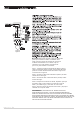
Installation Sheet


©2021 PL Sourcing, Inc. 012021
7775698
FF425HBN
42" Five-Blade Hugger Mount
Ceiling Fan,Brushed Nickel
ceiling fan installation and
operation instruction
read and save these instructions
Abano de Cinco Hojas de Montaje
Hugger, 42”, NÍQUEL CEPILLADO
7775698
INSTRUCCI
OPERACIÓN DE ABANO
N DE INSTALACIÓN Y
Ó
LEA Y GUARDE ESTAS INSTRUCCIONES
SAFETY INFORMATION
INFORMACIÓN DE SEGURIDAD
1
WARNING:
circuit panel before you begin the fan installation or before servicing the fan or installing accessories.
1. Read all instructions safety information care fully before installing your fan and save these instructions.
CAUTION: To avoid personal injury,the use of gloves may be necessary while handing fan parts with sharp
edges.
2. Make sure all electrical connections comply with Local Codes or Ordinances, the National Electrical
and ANSI/NFPA 70-1999. If you are unfamiliar with electrical wiring or if the house /building wires
are
different
colors than those referred to in the instructions,please use a qualified electrician.
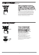
3. Make sure you have a location selected for your fan that allows clear space for the blades to rotate, and
atleast seven (7) feet (2.13 meters) of clearance between the floor and the fan blade tips. The fan should
be mounted so that the tips of the blades are at least thirty (30) inches (76 centimeters) from walls or other
upright structures.
4. The outlet box and ceiling support joist used must be securely mounted and capable of supporting at
least 35 pounds (16 kilograms). The oulet box must be supported di rectly by the building structure Use only
ETL or UL listed outlet boxes marked “FOR FAN SUPPORT .”
WARNING: To reduce the risk of fire,electrical shock,or personal injury,mount to the outlet box marked
"Acceptable for Fan Support," and use the mounting screws provided with the outlet box.Most outlet boxes
commonly used for the support of lighting fixtures are not acceptable for fan support and may need to be
replaced. Consult a qualified electrician if in doubt.
WARNING: To reduce the risk of fire,electrical shock,or personal injury,wire connectors provided with this fan
are designed to accept only one12 gauge house wire and two lead wires from the fan. If your house wire
is larger
than 12 gauge or there is more than one house wire to connect to the two fan lead wires, consult an
electrician
for the proper size wire connectors to use.
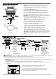
5. Electrical diagrams are for reference only. Light kits that are not packed with the fan must be ETL or ULlisted
and marked suitable for use with the model fan you are installing. Switches must be ETL or UL eneral use
switches. Refer to the instructions packaged with the light kits and switches for proper assembly.
To reduce the risk of electrical shock,turn off the electricity to the fan at the main fuse box or
.
Code,
tobe
6. After installation is complete,check that all connections are absolutely secure.
7. After making electrical connections,spliced conductors should be turned upward and pushed carefully up
into the outlet box. The wires should be spread apart with the grounded conductor and the
equipment-grounding conductor on opposite sides of the outlet box.
WARNING: To reduce the risk of electrical shock,fire and to prevent humming noise do not use this fan with any
solid state speed control device or control fan speed with a full range dimmer switch.[Using a full range dimmer
switch to control fan speed will cause a loud humming noise from fan.] (Note: This fan issuitable for use with
remote control.)
8. Do not operate the reverse switch until fan has come to a complete stop.
9. Do not insert anything between the fan blades while they are rotating.