AIR CONDITIONING SYSTEMS MODEL PUHY-P-Y(S)HA PFAV-P-VM-E(-F) DATA BOOK
Contents !. General Cautions 1. Indoor Unit Line-up·········································1 2. Temperature range ·········································2 3. Notes on selecting equipments·····················3 (1) Notes on using the Fresh Air Intake type units ! !. Indoor Unit 1. Specifications··················································5 (1) Standard type (2) Fresh air intake type 2. External dimensions·······································7 (1) Standard type (2) Fresh air intake type 3.
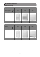
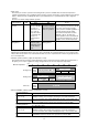
!. General Cautions 1. Indoor Unit Line-up Model type Model size Nominal HP Nominal cooling cap. *1 kW Nominal heating cap. *2 kW Floor standing PFAV-P-VM-E Connectable outdoor unit type P250 10HP 25.0 28.0 Standard type P500 20HP 50.0 56.0 P750 30HP 71.0 80.0 PUHY-P250YHA PUHY-P500YHA PUHY-P750YHA P300 10HP 28.0 26.5 Fresh air intake type P600 20HP 56.0 50.0 P900 30HP 80.0 71.0 PUHY-P250YHA PUHY-P500YHA PUHY-P750YHA *Nominal conditions *1,*2 are referable at the Specification sheet.
2. Temperature range Standard type Cooling Heating Indoor temperature Wet-bulb temperature 10~25˚C [50~77˚F] (Note 1) Dry-bulb temperature 15~28˚C [59~82˚F] Outdoor temperature Dry-bulb temperature -5~43˚C [23~109˚F] Wet-bulb temperature -20~15.5˚C [-4~60˚F] Note 1. If units are operated for a long time at the dew point temperature of 23˚C [73˚F] or more, condensate may collect and drip from the indoor units.
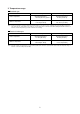
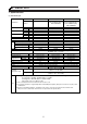
3. Notes on selecting equipments (1) Notes on using the Fresh Air Intake type units 1Fresh air intake type indoor units supply pretreated outside air into the room. This type of units are not designed to handle internal thermal load. Use other types of air conditioning units (e.g., CITY MULTI system) that are capable of handling internal thermal load in combination with the Fresh Air Intake type units.
4Fan control The unit may be forced to operate in the heating mode to prevent cold draft when the return air temperature (outside air temperature sensor reading) reaches 5˚C[41˚F] or below. At the time of factory shipment, fan setting is made so that the fan will stop during the defrost cycle and when there is a problem with the entire refrigerant systems. See below for switch settings and unit operation.
! !. Indoor Unit 1. Specifications (1) Standard type Indoor Model Name PFAV-P250VM-E PUHY-P250YHA(-BS) Outdoor Cooling Heating Cooling Heating Cooling Heating PFAV-P500VM-E PFAV-P750VM-E PUHY-P500YSHA(-BS) (PUHY-P250YHA(-BS) x 2, CMY-Y100VBK2) PUHY-P750YSHA(-BS) (PUHY-P350YHA(-BS) + PUHY-P400YHA(-BS), CMY-Y200VBK2) 25.0 (Maximum28.0) 50.0 (Maximum56.0) 71.0 (Maximum 80.0) 28.0 (Maximum 31.5) 56.0 (Maximum 63.0) 80.0 (Maximum 90.0) 7.46 / 7.53 17.85 / 18.84 26.33 / 27.40 System Power input 8.27 / 8.
(2) Fresh air intake type Indoor Model Name PFAV-P300VM-E-F PUHY-P250YHA(-BS) Outdoor Cooling Heating Cooling Heating Cooling Heating PFAV-P600VM-E-F PFAV-P900VM-E-F PUHY-P750YSHA(-BS) PUHY-P500YSHA(-BS) (PUHY-P250YHA(-BS) x 2, (PUHY-P350YHA(-BS) + PUHY-P400YHA(-BS), CMY-Y100VBK2) CMY-Y200VBK2) 28.0 (Maximum 33.5) 56.0 (Maximum 67.0) 80.0 (Maximum 100.0) 26.5 (Maximum 28.0) 50.0 (Maximum 56.0) 71.0 (Maximum 80.0) 6.73 / 6.72 14.69 / 15.05 22.54 / 22.74 System Power input 7.57 / 7.56 15.43 / 15.79 21.
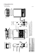
456 4 Designation Refrigerant pipe···ø22.2 brazed Refrigerant pipe···ø9.52 brazed Drain hole······Rc 1 Power supply wiring hole······ø43 Wiring hole······ø27 Wiring hole(The outdoor unit connection,Transmission line)······ø27 Earth terminal(installed in the control box)···M5 For mounting anchor bolt 4-ø12 Holes 7 5 6 Front air inlet 5 6 Remote controller 8 4 385 485 92 185 105 Notes 1.Be sure to wire the transmission line and power line separately. 2.
8 NO. 1 2 3 4 5 6 7 8 100 100 4 3 8 90 440 40 Designation Refrigerant pipe···ø28.5 brazed Refrigerant pipe······ø15.88 brazed Drain hole······Rc 1 1/4 Power supply wiring hole···ø52 Wiring hole······ø37 Wiring hole(The outdoor unit connection,Transmission line)···ø27 Earth terminal(installed in the control box)···M5 For mounting anchor bolt 4-ø12 Holes 5 2 602 6 1 9 Secure the proper space for installation work such as piping and wiring separately.
NO. 1 2 3 4 5 6 7 8 1 12 100 83 30 261 140 191 5 6 490 (50) 7 8 10 Supply air duct flange 200 Designation Refrigerant pipe···ø34.93 brazed Refrigerant pipe···ø19.05 brazed Drain hole······Rc 1 1/4 Drain hole······Rc 1 Wiring hole······ø62 Wiring hole(The outdoor unit connection,Transmission line)······ø38 Earth terminal(installed in the control box)······M5 For mounting anchor bolt 4-ø15 Holes 2 110X4=440 606(Size on inside) 20-ø4.
NO. 1 2 3 4 5 6 7 8 4 3 456 5 1 7 6 2 1182 Supply air duct flange 1200 1262 1234 19 7 Remote controller 8 28-ø3 Holes 20 40 5 6 4 385 485 1126 92 105 185 Notes 1.Be sure to wire the transmission line and power line separately. Designation 2.When the room in which the unit is installed is airtight, Refrigerant pipe···ø22.2 brazed the pressure in the room may become negative. Refrigerant pipe···ø9.
100 50 1 NO. 1 2 3 4 5 6 7 8 8 90 440 40 Designation Refrigerant pipe···ø28.5 brazed Refrigerant pipe···ø15.88 brazed Drain hole········Rc 1 1/4 Power supply wiring hole·······ø52 Wiring hole·····ø37 Wiring hole(The outdoor unit connection,Transmission line)······ø27 Earth terminal(installed in the control box)···M5 For mounting anchor bolt 4-ø12 Holes 602 4 3 6 5 1000 2 9 Secure the proper space for installation work such as piping and wiring separately.
NO. 1 2 3 4 5 6 7 8 1 12 100 83 30 261 140 191 5 6 490 (50) 7 8 10 Supply air duct flange 200 Designation Refrigerant pipe···ø34.93 brazed Refrigerant pipe···ø19.05 brazed Drain hole······Rc 1 1/4 Drain hole······Rc 1 Wiring hole······ø62 Wiring hole(The outdoor unit connection,Transmission line)······ø38 Earth terminal(installed in the control box)······M5 For mounting anchor bolt 4-ø15 Holes 2 110X4=440 606(Size on inside) 20-ø4.
3.
14 TH21 t˚ 1 TH22 2 CN21 t˚ TH23 1 CN29 2 0 1 3 2 1 CN31 SW1 CN60 LEV1 M 6 5 4 3 2 1 6 5 4 3 2 1 ❈ P250 7 6 5 4 3 2 1 CN7V Note: 1. (Heavy dotted line):Field wiring 2. Have all electric work done by a licensed electrician according to the local regulations. 3. Earth leakage circuit breaker should be set up on the wiring of the power supply. 4. Mark indicates terminal bed, connector. 5.
EF 012 BCD 8 67 9A 15 7 8 0 1 9 0 1 9 SWC SW5 SW8 SW14 SW12 SW11 t˚ 2 1 t˚ 2 1 TH21 TH22 TH23 2 1 3 2 1 SW1 SW7 SW2 SW3 CN20 CN21 CN29 CN31 t˚ 7 8 M M 7654321 CN7V 52F X2 M LEV3 654321 654321 CN60 X4 LEV1 654321 654321 X1 654321 7654321 LEV2 CN60 CN7V 3 3 1 T CN3T 1 T CN3T 3 1 CNT F 51F 3 1 CNT F Note: 1. (Heavy dotted line):Field wiring 2. Have all electric work done by a licensed electrician according to the local regulations. 3.
16 t˚ TH21 2 1 t˚ TH22 2 t˚ 1 TH23 TH24 2 1 2 CN22 CN29 t˚ SW3 0 1 LEV1 M 6 5 4 3 2 1 6 5 4 3 2 1 CN60 3 CN3T T 1 3 1 CNT F 1 U 5 M 3~ Fan motor 3 CND ZNR 1 51F X4 3 CN33 52F 51F CN90 XO5 XO4 1 3 5 7 9 XO6 52F CN2M CN3A Indoor controller board 1 TB2 N L3 L2 L1 TB5 Earth M1 M2 S (Shield) 2 2 Symbol TH21 TH22 TH23 TH24 SW1 SW2 SW3 SW4 SW5 SW7 SW8 SW11 SW12 SW14 SWC SWE 1 2 3 1 TB15 Inside section of control box Symbol explanation Symbol Na
t˚ EF 0 12 2 1 17 2 1 2 1 t˚ 2 1 t˚ 2 1 TH22 TH23 TH24 t˚ 9 0 1 3 2 1 654321 7654321 M LEV3 654321 CN60 X4 CN7V 52F X2 3 1 T CN3T CN3T LEV1 M X1 M LEV2 654321 654321 3 CN60 654321 7654321 CN7V 1 T 3 1 CNT F 51F 3 1 F1 X1 M 3~ 51F 13 57 9 52F CNP CN2M CN90 X05 X04 X2 13 CND CN33 ZNR CN90 X05 X04 1 3 57 9 X06 CNP CN2M CN3A Indoor controller board No.2 13 CND CN33 ZNR 1 3 5 U 1 3 5 U CNT F X06 CN3A Indoor controller board No.
5. Sound Pressure Levels (1) Standard type •PFAV-P250VM-E 1m Power sorce : 3N 380/400/415V 50/60Hz 1m Measurement location 50Hz, OCTAVE BAND PRESSURE LEVEL (dB) 0 dB=20µPa 90 60Hz NC Curve 80 70 NC-70 60 NC-60 50 NC-50 NC-40 40 30 NC-30 20 NC-20 10 ·Approximate minimum audible limit on continuous noise. 63 125 250 500 63Hz 125Hz 250Hz 50Hz 68 63 59 500Hz 1000Hz 2000Hz 4000Hz 8000Hz dB(A) 50 46.5 45.5 36 32 55 60Hz 66 63 58.5 51 47.5 44 38.
•PFAV-P750VM-E 1m Power sorce : 3N 380/400/415V 50/60Hz 1m Measurement location 50Hz/60Hz OCTAVE BAND PRESSURE LEVEL (dB) 0 dB=20µPa 90 NC Curve 80 70 NC-70 60 NC-60 NC-50 50 40 NC-40 30 NC-30 20 NC-20 10 ·Approximate minimum audible limit on continuous noise. 63 125 250 500 63Hz 125Hz 250Hz 50Hz 72.5 63.5 62.5 500Hz 1000Hz 2000Hz 4000Hz 8000Hz dB(A) 62.5 60 56 49 44.5 65 60Hz 72.5 63.5 62.5 62.5 60 56 49 44.
•PFAV-P600VM-E-F 1m Power sorce : 3N 380/400/415V 50/60Hz 1m Measurement location 50Hz, OCTAVE BAND PRESSURE LEVEL (dB) 0 dB=20µPa 90 60Hz NC Curve 80 70 NC-70 60 NC-60 50 NC-50 40 NC-40 NC-30 30 NC-20 20 10 ·Approximate minimum audible limit on continuous noise. 63 125 250 500 63Hz 125Hz 250Hz 50Hz 67 60.5 51 500Hz 1000Hz 2000Hz 4000Hz 8000Hz dB(A) 45.5 41 34.5 27.5 17 50 60Hz 69.5 61.5 54.5 49 46.5 41 34.
6.
7. Fan characteristic curves (1) Standard type •PFAV-P250VM-E 50Hz ······Standard 900 800 1 2 700 3 Total static pressure < Pa > 4 5 2.2kW 600 6 7 8 500 9 10 400 11 12 13 300 18 14 15 16 17 19 Internal resistance 20 21 22 23 200 100 0 70 75 80 85 90 95 100 105 110 Airflow rate < m3 / min > 60Hz ······Standard 900 800 1 2 700 3 Total static pressure < Pa > 4 5 2.
Specification(Pulley , Belt ) Standard(Factory set) <50Hz> Motor pulley Motor Pitch diameter (Changeability) 2.2kW 140.2 Fan pulley Bore (E) <ø> Nominal diameter (B) <ø> Bore (E) <ø> V-belt (H) Over current relay (Fan motor) 28 212 20 1423 / 56 5.0A Motor 2.
Variable-width pulley PC ø table Number of Pulley distance turns to apply (mm) 0 (0) 1/4 (0.4) 1/2 (0.8) 3/4 (1.1) 1 (1.5) 1·1/4 (1.9) 1·1/2 (2.3) 1·3/4 (2.6) 2 (3.0) 2·1/4 (3.4) 2·1/2 (3.8) 2·3/4 (4.1) 3 (4.5) 3·1/4 (4.9) 3·1/2 (5.3) 3·3/4 (5.6) 4 (6.0) 4·1/4 (6.4) 4·1/2 (6.8) 4·3/4 (7.1) Pulley Fixed disc must be placed on the motor side. PC ø of variable-width pulleys for 2.2kW motor 150.0 148.8 147.5 146.3 145.1 143.9 142.6 141.4 140.2 139.0 137.7 136.5 135.3 134.1 132.8 131.6 130.4 129.1 127.9 126.
•PFAV-P500VM-E 50Hz ······Standard 800 700 1 2 600 Total static pressure < Pa > 3 500 4 5 400 6 5.5KW 7 300 8 9 Internal resistance 10 200 100 0 140 150 160 170 180 190 200 210 220 230 240 Airflow rate < m3 / min > 60Hz ······Standard 800 700 1 600 Total static pressure < Pa > 2 500 3 4 400 5 5.
Specification(Pulley , Belt ) Standard(Factory set) <50Hz> Motor pulley Motor Nominal diameter (B) <ø> 5.5kW 118 Fan pulley Bore (E) <ø> Nominal diameter (B) <ø> Bore (E) <ø> V-belt (H) Over current relay (Fan motor) 38 236 32 1042 / 41 11A Motor 5.
Shape of the pulley (unit:mm) (keyway) 5.5 Rz 3 Rz 3 .2 12.5 12.5 Rz 6.3 19 G Rz 6.3 Rz 3.2 .2 Rz 3.2 Rz 6.3 9.5 Rz 6.3 F A (d:Pulley outside diameter) C Rz 3.2 D Rz 6.3 B (dm:Pulley nominal diameter) M8 11 E Belt dm:Pulley nominal diameter dm 160 161 < dm 200 201 < dm 34˚ 36˚ 38˚ 44 59 11.0 16.5 40˚ H (outer center) * See p.40 for "How to choose the pulley.
•PFAV-P750VM-E 50Hz ······Standard 1100 1 1000 2 900 3 800 Total static pressure < Pa > 4 700 5 600 6 500 7 8 400 300 9 10 11 7.5kW 12 200 13 Internal resistance 100 0 220 240 260 280 300 320 340 Airflow rate < m3 / min > 60Hz ······Standard 1100 1 1000 900 Total static pressure < Pa > 800 700 600 2 3 4 5 6 7 500 400 8 9 10 300 11 7.
Specification(Pulley , Belt ) Standard(Factory set) <50Hz> Motor pulley Motor Nominal diameter (B) <ø> 7.5kW 145 Fan pulley Bore (E) <ø> Nominal diameter (B) <ø> Bore (E) <ø> V-belt (H) Over current relay (Fan motor) 38 300 32 1347 / 53 15A Motor 7.
Shape of the pulley (unit:mm) (keyway) 5.5 Rz 3 Rz 3 .2 12.5 12.5 Rz 6.3 19 G Rz 6.3 Rz 3.2 .2 Rz 3.2 Rz 6.3 9.5 Rz 6.3 F A (d:Pulley outside diameter) C Rz 3.2 D Rz 6.3 B (dm:Pulley nominal diameter) M8 11 E Belt dm:Pulley nominal diameter dm 160 161 < dm 200 201 < dm 34˚ 36˚ 38˚ 44 59 11.0 16.5 40˚ H (outer center) * See p.40 for "How to choose the pulley.
(2) Fresh air intake type •PFAV-P300VM-E-F 50Hz ······Standard 800 1 700 1.5kW 2 600 3 4 Total static pressure < Pa > 5 6 500 7 8 9 10 400 11 12 13 14 300 15 16 17 18 19 20 200 21 22 23 24 25 100 Internal resistance 0 36 40 45 50 54 Airflow rate < m3 / min > 60Hz ······Standard 800 700 1.
Specification(Pulley , Belt ) Standard(Factory set) <50Hz> Motor pulley Motor Pitch diameter (Changeability) 1.5kW 140 Motor pulley Rotational Outside Slide peace No. speed Bore (E) Rotation diameter <ø> number <ø> 1 1600 149 2 24 Fan pulley Bore <ø> Nominal diameter (B) <ø> Bore (E) <ø> V-belt (H) Over current relay (Fan motor) 24 280 20 1499 / 59 3.6A Motor 1.5kW,1450rpm <50Hz> Fan pulley Outside Nominal (F) (G) diameter (A) Diameter (B) (C) <ø> <ø> <ø> 27.
Variable-width pulley PC ø table Number of Pulley distance turns to apply (mm) 0 (0) 1/4 (0.4) 1/2 (0.8) 3/4 (1.1) 1 (1.5) 1·1/4 (1.9) 1·1/2 (2.3) 1·3/4 (2.6) 2 (3.0) 2·1/4 (3.4) 2·1/2 (3.8) 2·3/4 (4.1) 3 (4.5) 3·1/4 (4.9) 3·1/2 (5.3) 3·3/4 (5.6) 4 (6.0) 4·1/4 (6.4) 4·1/2 (6.8) 4·3/4 (7.1) Pulley Fixed disc must be placed on the motor side. PC ø of variable-width pulleys for 2.2kW motor 140.0 138.8 137.5 136.3 135.1 133.9 132.6 131.4 130.2 129.0 127.7 126.5 125.3 124.1 122.8 121.6 120.4 119.1 117.9 116.
•PFAV-P600VM-E-F 50Hz ······Standard 700 600 1 Total static pressure < Pa > 500 2 3 2.2KW 400 4 5 6 300 7 8 9 200 10 11 12 13 100 Internal resistance 0 72 80 90 100 108 Airflow rate < m3 / min > 60Hz ······Standard 700 600 1 Total static pressure < Pa > 500 2 3 2.
Specification(Pulley , Belt ) Standard(Factory set) <50Hz> Motor pulley Motor Nominal diameter (B) <ø> 2.2kW 118 Fan pulley Bore (E) <ø> Nominal diameter (B) <ø> Bore (E) <ø> V-belt (H) Over current relay (Fan motor) 28 300 32 1194 / 47 5.0A Motor 2.2kW,1450rpm <50Hz> Motor pulley Rotational Outside Nominal speed diameter (A) Diameter (B) <ø> <ø> 129 118 1 1016 129 118 961 2 No.
Shape of the pulley (unit:mm) Rz 3.2 Rz 6.3 ko .2 Rz 6.3 Rz 6.3 C D F Rz 12.5 A (d : Pulley outside diameter) 11 B (dm : Pulley nominal diameter) M8 Rz 3.2 G Rz 3.2 .2 Rz 3 k m Rz 3 E Belt 25 dm:Pulley nominal diameter dm 160 161 < dm 200 201 < dm 34˚ 36˚ 38˚ m k ko e 12.5 5.5 9.5 12.5 40 16.5 11.0 Rz 6.3 (keyway) e 40˚ H (outer center) * See p.40 for "How to choose the pulley.
•PFAV-P900VM-E-F 50Hz 60Hz ······Standard ······Standard 1000 1000 3.7kW 3.
Specification(Pulley , Belt ) Standard(Factory set) <50Hz> Motor pulley Motor Nominal diameter (B) <ø> 3.7kW 125 Fan pulley Bore (E) <ø> Nominal diameter (B) <ø> Bore (E) <ø> V-belt (H) Over current relay (Fan motor) 28 315 32 1423 / 56 7.5A Motor 3.7kW,1450rpm <50Hz> Fan pulley Motor pulley Rotational Outside Nominal speed diameter (A) Diameter (B) <ø> <ø> 223 212 1025 1 223 212 976 2 No.
Shape of the pulley (unit:mm) (keyway) Rz 3 Rz 3 .2 12.5 12.5 5.5 Rz 6.3 19 G Rz 6.3 Rz 3.2 .2 Rz 3.2 Rz 6.3 9.5 Rz 6.3 F A (d:Pulley outside diameter) C Rz 3.2 D Rz 6.3 B (dm:Pulley nominal diameter) M8 11 E Belt dm:Pulley nominal diameter dm 160 161 < dm 200 201 < dm 34˚ 36˚ 38˚ 44 59 11.0 16.5 40˚ H (outer center) * See p.40 for "How to choose the pulley.
How to choose the pulley (EXAMPLE) Indoor unit : PFAV-P750VM-E (50Hz) Required external static pressure : 600 Pa Required air flow rate : 250m3/min 50Hz ······Standard The fan characteristic curve shows the internal resistance is 100 Pa when the air flow rate is 250m3/min. Total static pressure = internal resistance + external static pressure =100 Pa + 600 Pa =700 Pa Read the intersection point of the total static pressure 700 Pa and the air flow rate 250m3/min in the fan characteristic curve.
8. Optional parts (1) Plenum chamber PAC-CC83PL-E mm For P250 indoor unit 1200 410 395 485 260 10- 3 Holes 65 Branch duct hole (Knockout) 150 150 65 385 210 Air outlet PAC-CC85PL-E mm For P500 indoor unit 1420 410 505 55 635 170 260 55 70 60 10- 3 Holes 65 150 Branch duct hole (Knockout) 150 65 495 Side air outlet 310 Air outlet PAC-CC87PL-E mm For P750 indoor unit 741 1750 486 Air outlet Note: The assembly operation is necessary for this plenum.
! ! !. Outdoor Unit 1. Specifications Model Power source Sound pressure level (measured in anechoic room) Refrigerant Liquid pipe piping diameter Gas pipe Set Model Model FAN Type x Quantity Air flow rate PUHY-P250YHA(-BS) 3-phase 4-wire 380-400-415V 50/60Hz 57 dB mm (in.) 9.52(3/8) Brazed (12.7(1/2) Brazed,total length >= 90m) mm (in.) 22.2(7/8) Brazed — Propeller fan x 1 m3 / min 185 3,083 L/s 6,532 cfm Inverter-control, Control, Direct-driven by motor Driving mechanism 0.
2.
•PUHY-P350,400YHA(-BS) Unit:mm 44
•PUHY-P500YSHA(-BS) Unit:mm 45
•PUHY-P750YSHA(-BS) Unit:mm 46
3.
4.
5.
•PUHY-P750YSHA(-BS) 1m 1m Measurement location 50
6. Optional parts (1) Outdoor twinning kit For PUHY-P-YSHA, following optional Outdoor Twinning Kit is needed to use to combine to refrigerant flows of its PUHY-P-YHA. Details of selecting the proper kit should be referred to VII. Piping Design.
! %. Capacity Tables (1) Correction by temperature • P500 • Cooling capacity • Cooling capacity 1.3 1.4 1.2 1.3 1.1 15 1.0 16 18 20 22 24 0.9 0.8 Ratio of cooling capacity Ratio of cooling capacity 1Cooling • P250 15 1.1 16 1.0 18 20 0.9 22 24 0.8 0.7 0.7 -5 0 5 10 15 20 25 30 35 40 -5 45 • Cooling input 0 5 10 25 30 35 40 45 1.0 0.9 0.8 Ratio of power input 1.1 15 16 18 20 22 24 1.1 1.0 0.9 0.8 0.7 0.7 0.6 0.6 0.5 0.4 0.
2Heating • P250 • P500 • Heating capacity • Heating capacity 1.4 1.3 1.2 15 Ratio of heatling capacity Ratio of heatling capacity 1.3 1.2 1.1 20 1.0 0.9 25 0.8 0.7 27 0.6 15 1.1 1.0 20 0.9 0.8 25 0.7 27 0.6 0.5 0.5 0.4 0.4 -20 -15 -10 -5 0 5 10 15 -20 • Heating input -15 -10 -5 0 5 10 15 • Heating input 1.1 1.1 15 1.0 Ratio of power input Ratio of power input 1.0 0.9 0.8 20 0.7 25 0.6 0.8 20 0.7 25 0.6 27 0.5 27 0.
(2) Correction at frost and defrost Due to frost at the outdoor heat exchanger and the automatic defrost operation, the heating capacity of the outdoor unit can be calculated by multiplying the correction factor shown in the table below. Table of correction factor at frost and defrost Outdoor inlet air temp. ˚C Outdoor inlet air temp. ˚F PUHY-P250YHA (-BS) PUHY-P500YSHA (-BS) PUHY-P750YSHA (-BS) 6 43 1.00 1.00 1.00 4 39 0.95 0.98 0.98 2 36 0.84 0.89 0.89 1 34 0.83 0.87 0.
(4) Correction by indoor unit airflow rate • P250 • P500 • Cooling • Cooling 1.10 Capacity / input correction factor Capacity / input correction factor 1.10 1.00 0.90 0.90 70 80 90 Airflow rate (m3/min) 100 110 150 160 170 180 210 220 230 240 220 230 240 Capacity / input correction factor 1.10 1.00 0.90 1.00 0.90 70 80 90 Airflow rate (m3/min) 100 110 150 160 170 180 190 200 210 Airflow rate (m3/min) *1.Solid line indicates capacity correction factor *2.
(5) Input correction by capacity • P250 • P300-E-F • Cooling • Cooling 1.00 Cooling input correction factor Cooling input correction factor 1.00 0.90 0.80 0.70 0.60 0.50 0.40 0.80 0.70 0.60 0.50 0.40 50% 60% 70% 80% 90% Ratio of cooling capacity (*1) 100% • Heating 50% 60% 70% 80% 90% Ratio of cooling capacity (*1) 100% 50% 60% 90% 100% 50% 60% 70% 80% 90% Ratio of cooling capacity (*1) 100% 50% 60% 100% • Heating 1.00 1.
(6) Bypass factor • P750 0.40 0.40 0.30 0.30 Bypass factor Bypass factor • P250 0.20 0.10 0.20 0.10 0.00 70 80 90 Airflow rate (m3/min) 100 0.00 210 110 • P500 230 250 270 290 310 Airflow rate (m3/min) 330 350 • P300-E-F 0.50 0.30 Bypass factor Bypass factor 0.40 0.30 0.20 0.20 0.10 0.10 0.00 0.00 150 160 170 180 190 200 210 Airflow rate (m3/min) 220 230 35 240 45 50 55 Airflow rate (m3/min) • P600-E-F • P900-E-F 0.30 0.30 0.20 0.
%. Controller 1. Local remote controller (1) MA Remote controller PAR-21MAA : built-in the indoor unit. Functions Item ON/OFF TIME SUN MON TUE WED THU FRI SAT TIMER Hr ON AFTER AFTER OFF ERROR CODE FUNCTION FILTER WEEKLY SIMPLE AUTO OFF ONLY1Hr. TEMP. Operation mode switching ON/OFF TEMP. MENU BACK PAR-21MAA MONITOR/SET ON/OFF FILTER DAY CLOCK Temperature setting CLEAR • Dot matrix liquid crystal screen displays complete operating status.
% !. System Design 1. Outdoor Installation (1) Requirement on installation site 1 2 3 4 5 6 7 8 No direct thermal radiation to the unit; No possibility of annoying the neighbors by the sound of the unit; Avoid the sites where strong winds blow. With strength to bear the weight of the unit; Drain flow from the unit is cared at heating mode; Enough space for installation and service as shown at (2); Avoid the sites where acidic solutions or chemical sprays (sulfur series)are used frequently.
(2) Spacing • PUHY-P250YHA(-BS) 60
• PUHY-P350, 400YHA(-BS) 61
(3) Piping direction 1 Lifting method ¥ When lifting the unit with ropes, run the ropes under the unit and use the lifting hole. ¥ Support the unit at four points with two ropes, and avoid giving mechanical shock. ¥ Suspension rope angle must be 40û or less, so as to avoid compressing fan guard. ¥ Use two ropes, each at least 8m [26 ft.] in length ¥ Use ropes strong enough to support the weight of the unit. ¥ Always suspend the unit from four corners.
2 IInstallation When the pipes and/or cables are routed at the bottom of the unit, make sure that the through hole at the base of the unit does not get blocked with the installation base. When the pipes are routed at the bottom of the unit, the base should be at least 100 mm [3-15/16 in.] in height.
4 Installation 6 7 8 9 6 6 8 & : 8 : 8 ' 8 6 + : 8 6
6 Twinning on the outdoor unit side • The tilt angle of the twinning pipe The tilt angle of the twinning pipe must be within ±15 ° with the horizontal plane. Tilting the twinning pipe more than specified will cause damage to the unit. • The length of the straight part of the pipe before the branching For the twinning kit, always use the accessory piping parts. The length of the straight part of pipe connected in front of the twinning pipe must be 500 mm [19 in.] or longer.
7 Twinning on the outdoor unit side See the following drawing for connecting the pipes between the outdoor units. Field piping Twinning kit Field piping The le mus ngth of t be t 500 he straig mm h [19 i t pipe n.] o r lon ger CAUTION The length of the straight pipe must be 500mm [19 in.] or longer. If not, it may cause improper operation.
(4) Weather countermeasure In cold and/or snowy areas, sufficient countermeasures to wind and snow damages should be taken for operating unit in normal and good condition in winter time. Surround the units with snow nets or fences to protect them from snow. Even in the other areas, full consideration is required for installation of unit in order to prevent abnormal operations caused by wind or snow.
Countermeasure to wind Referring to the figure shown below, take appropriate measures which will suit the actual situation of the place for installation. A unit installed alone is vulnerable to strong winds. Select the installation site carefully to minimize the effect of winds. To install a unit in a place where the wind always blows from the same direction, install the unit so that the outlet faces away from the direction of the wind.
2.
(2) Spacing • PFAV-P250,500VM-E 300 Optional plenum chamber Duct space (if a duct is connected) (Unit mm) P250: 800 or more P500: 1000 or more (Front space) Through hole for the remote controller wiring to outdoor unit Refrigerant pipes Wire hole for the device power supply P250: 500 or more P500: 100 or more 100 or more Wood base 85 or more Drain pipe Power cable hole (380V or more) 50 or more • PFAV-P300,600VM-E-F 300 Duct space (if a duct is connected) (Unit mm) (Front space) Through h
• PFAV-P750VM-E • PFAV-P900VM-E-F (Unit mm) 1000 or more A (Front space) B Remote controller cable hole (to outdoor unit) Power cable hole (380V ormore) 750 or more 500 or more 85 or more Refrigerant pipe (liquid) Wood base 400 or more • Select a solid surface, and install the unit on a wood base at least 8.5 cm in thickness to allow for proper discharge of drain water and to prevent vibration from the air conditioning units from being transmitted to the floor.
(3) Installing the Indoor Unit WARNING Install the unit on a level surface. • If the unit is installed on an incline, water leakage or malfunctions may result. Check for straightness with a level. WARNING Do not stand on the unit. • You may fall down or the item may fall, causing injury. CAUTION Properly dispose of packing materials. • Pallets and the nails on the pallets can pose the risk of injury. • Plastic bags can pose suffocation and choking hazards: keep out of the reach of children.
Notes on when an optional plenum chamber is installed The unit described in this manual is designed to be used with a duct. When an Optional plenum chamber is used, an adjustment of the pulley is required. • Refer to the manual that came with the plenum chamber for how to install it.
Important notes on pulleys and pulley belts • Adjusting the variable-width pulley Adjust the PC ø of variable-width pulley according to the procedures described below. 1) Loosen the setscrew holding the fixed and the sliding discs in place. 2) Turn the sliding disc counter-clockwise until no gap is left (0 mm) between the fixed and the sliding discs. 3) Select the PC ø in Table 1 that is closest to the one to be used.
• Horizontal pulley alignment and proper belt tension 1) The fan pulley and the motor pulley must be aligned to meet the criteria shown in Figure 1 and Table 1. 2) Set the tension for the V-belt so that the deflection force falls within the range as shown in the table in! !7. 3) After the belt has been broken in on the pulley (after 24 to 28 hours of operation), check the belt for looseness and adjust the belt tension as specified in step (2) above as necessary.
(4) Separating the indoor unit to allow for easy transportation Instructions for separating the P500, P600-F indoor unit into parts The indoor unit can be separated into the base block, fan block, and other parts. Place the unit on a level surface before separating the unit. Base block net weight The dimension of the base block after it is separated from the other parts is Net weight marked with ✻ in the figure below.
• Instructions for separating the P750, P900-F indoor unit into parts The heat exchanger block can be separated from the main body of indoor unit (Brazing is required). Place the unit on a level surface before separating the unit. indicates the surface to split up. The dimensions of the base block after being separated from the heat exchanger block are marked with ✻ in the figure below.
f. Remove supporting plates 13 on both sides of the drain pan B 12 . This is the separation process. Use caution not to damage or scratch the unit during transportation. Take extra precautions when transporting the heat exchanger to prevent damaging its fin or heat transfer tube from shock. 2) Reassemble in the reverse order as above. Replace all fixing screws and bolts back in, and tighten each of them to the proper tightening torque.
(5) Internal diagram • PFAV-P250VM-E • PFAV-P300VM-E-F Fan Material: Hot-dip galvanized steel sheet Outlet Material: Hot-dip galvanized steel sheet Rear panel Material: Hot-dip galvanized steel sheet Siroccofan Front panel (Upper) Material: Alloyed hot-dip galvanized steel sheet Pulley Materials: Gray cast iron Fan motor Material: Hot-rolled mild steel plate Remote controller Air filter Material: Synthetic non-woven fabric Indoor heat exchanger Material: Coil phosphorus deoxidized copper Fins aluminum
• PFAV-P750VM-E • PFAV-P900VM-E-F Fan motor Material: Hot-rolled mild steel sheet Pulley Material: Gray cast iron Heat exchanger Material: Coil phosphorus deoxidized copper Fins aluminum Fan Material: Hot-dip galvanized steel sheet Front panel (upper) Material: Alloyed hot-dip galvanized steel sheet Scroll dumper 10 3 2 5 4 Air filter Material: PP Honeycomb fabric V-belt Drain pan F Material: Alloyed hot-dip galvanized steel sheet Remote controller Control box Material: Hot-dip galvanized steel sh
% ! !. Piping Design 1. R410A Piping material Refrigerant pipe for PFAV shall be made of phosphorus deoxidized copper, and has two types. • Type-O : Soft copper pipe (annealed copper pipe), can be easily bent with human's hand. • Type-1/2H pipe : Hard copper pipe (Straight pipe), being stronger than Type-O pipe of the same radical thickness. The maximum operation pressure of R410A air conditioner is 4.30 MPa [623psi]. The refrigerant piping should ensure the safety under the maximum operation pressure.
2. Piping Design (1) PUHY-P250 Piping OU H' (OU under IU) H (OU above IU) Note1. If the A/C system is designed to use cooling mode under outdoor temperature 0˚C, H’<=15m. Note2. As bents cause pressure loss on transportation of refrigerant, fewer bents design is better; Piping length needs to consider the actual length and equivalent length which bents are counted. Equivalent piping length (m)=Actual piping length+"M" x Quantity of bent. IU A L1 IU : Indoor unit , OU : Outdoor unit Fig.
(2) PUHY-P500, 750 Piping 2 If the A/C system is designed to use cooling mode under outdoor temperature 0˚C, H’<=15m. ! ! ! " # $ $ $ % & $ $ $ '% & $ ()*+ $,- - .
(3) PUHY-P-Y(S)HA's refrigerant charging calculation Sample connection (with PFAV-P600VM-E-F) OU OU Note1. If the A/C system is designed to use Cooling-mode under Outside temperature 0˚C, H’<=15m. Note2. As bents cause pressure loss on transportation of refrigerant, fewer bents design is better; Piping length needs to consider the actual length and equivalent length which bents are counted. Equivalent piping length (m)=Actual piping length+"M" x Quantity of bent.
% ! ! !. Wiring Design 1. External wiring diagram (1) Power supply examples •PUHY-P250YHA + PFAV-P300VM-E-F Note12 Note: 1 The transmission cable is not-polarity double-wire. 2 Symbol means a screw terminal for wiring. 3 The shield wire of transmission cable should be connected to the grounding terminal at Outdoor unit.
•PUHY-P500YSHA + PFAV-P600VM-E-F Note12 Central control transmission cable >=1.25mm 2 Shield cable (CVVS, CPEVS MVVS) SC Connector CN41 CN40 Note4 Indoor-outdoor transmission cable >=1.
2. Electrical work (1) Power cable specifications Thickness of wire for main power supply, capacities of the switch and system impedance Model Outdoor unit indoor unit PUHY-P250YHA PUHY-P350YHA PUHY-P400YHA PFAV-P250 PFAV-P500 PFAV-P750 PFAV-P300-F PFAV-P600-F PFAV-P900-F Minimum wire thickness (mm2) Branch Ground Main cable 4.0 4.0 6.0 6.0 10.0 10.0 1.5 1.5 4.0 4.0 10.0 10.0 1.5 1.5 1.5 1.5 4.0 4.0 Breaker for current leakage 30A 100mA 0.1sec. or less 40A 100mA 0.1sec. or less 60A 100mA 0.1sec.
3. M-NET control Control wiring depends on system configurations. Be sure to read the section "4. An Example of a System to which an MA Remote Controller is connected" before starting wiring work. (1) Types and maximum allowable length of cables Control lines are categorized into two types: transmission line and remote controller line. Use the appropriate type of cables and observe the maximum allowable length specified for a given system.
1Address Setting The need for address settings and the address setting range depend on the system configuration. See "4. An Example of a System to which an MA Remote Controller is connected" for details.
4.
(2) Sample control wiring (Different refrigerant group operation) < < < > > > 91 Refer to the section 3.(2)1 "Address Setting.
(3) Sample control wiring (connect the system controller to the transmission cable for the centralized control) < > < < > > (* L2 + L31 + L4 + L32 200m [656ft]) Refer to the section 3.(2)1 "Address Setting.
5. System control (1) System control for the indoor units 1 Various start/stop control (Indoor unit setting) 1) The restart setting for the indoor unit can be set with the DIP SW (SW1-9, 10) on the unit. Function Setting(SW1)(Note 4) Operation recovery after power failure 9 10 Power reset (Notes 1, 2, and 3) Indoor unit will go into operation within approximately five minutes of power restoration regardless of its operation status before power off (or power failure).
3) Emergency Operation Mode a.
(b) a) b) b.
(2) System control for the outdoor units 1 Various types of control using input-output signal connector on the outdoor unit (various connection options) *6. Take out signals from the outdoor unit that is designated as OC if multiple outdoor units exist in a single system.
97
98
6. Caution for refrigerant leakage The installer and/or air conditioning system specialist shall secure safety against refrigerant leakage according to local regulations or standards. The following standard may be applicable if no local regulation or standard is available. (1) Refrigerant property R410A refrigerant is harmless and incombustible. The R410A is heavier than the indoor air in density. Leakage of the refrigerant in a room has possibility to lead to a hypoxia situation.
DATA BOOK PUHY-P-Y(S)HA PFAV-P-VM-E(-F) HEAD OFFICE: TOKYO BLDG., 2-7-3, MARUNOUCHI, CHIYODA-KU, TOKYO 100-8310, JAPAN http://Global.MitsubishiElectric.com MEE10K037 New publication effective Mar.