INVERTER Plug-in option FR-A7AP INSTRUCTION MANUAL Orientation control Encoder feedback control Vector control PRE-OPERATION INSTRUCTIONS 1 INSTALLATION 2 ORIENTATION CONTROL 3 ENCODER FEEDBACK CONTROL 4 VECTOR CONTROL 5
Thank you for choosing this Mitsubishi Inverter plug-in option. This instruction manual gives handling information and precautions for use of this equipment. Incorrect handling might cause an unexpected fault. Before using the equipment, please read this manual carefully to use the equipment to its optimum. Please forward this manual to the end user.
2. Injury Prevention 3) Usage WARNING CAUTION • Apply only the voltage specified in the instruction manual to each terminal. Otherwise, burst, damage, etc. may occur. • Ensure that the cables are connected to the correct terminals. Otherwise, burst, damage, etc. may occur. • Always make sure that polarity is correct to prevent damage, etc. Otherwise, burst, damage may occur. • While power is on or for some time after power-off, do not touch the inverter as it is hot and you may get burnt. 3.
CONTENTS 1 PRE-OPERATION INSTRUCTIONS 1.1 Unpacking and Product Confirmation .............................................................................................1 1.1.1 1.1.2 1.1.3 2 2.1 2.2 2.3 2.4 2.5 2.6 2.7 3 3.1 3.2 3.3 3.4 1 Packing confirmation ...................................................................................................................................... 1 SERIAL number check .................................................................................
4 4.1 4.2 4.3 5 5.1 5.2 5.3 5.4 II ENCODER FEEDBACK CONTROL 24 Wiring Examples ..............................................................................................................................24 Terminals ..........................................................................................................................................25 Encoder Feedback Control Parameter List ...................................................................................
1 1.1 PRE-OPERATION INSTRUCTIONS Unpacking and Product Confirmation Take the plug-in option out of the package, check the unit name, and confirm that the product is as you ordered and intact. This product is a plug-in option dedicated for the FR-A700 series. 1.1.1 Packing confirmation Check the enclosed items. Plug-in option Mounting screw (M3 × 6mm) Hex-head screw for option ......................................... 1 .............. 2 (Refer to page 5.) mounting (5.5mm) ...............
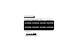
PRE-OPERATION INSTRUCTIONS 1.1.2 SERIAL number check The FR-A7AP can be used with the FR-A700 series having the following serial number or later. Check the SERIAL number indicated on the inverter rating plate or package. Model FR-A720-0.4K/0.75K FR-A720-1.5K/2.2K FR-A720-3.7K FR-A720-5.5K to 11K FR-A720-15K to 22K FR-A720-30K FR-A720-37K FR-A720-45K FR-A720-55K FR-A720-75K/90K SERIAL (Serial No.
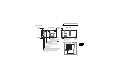
PRE-OPERATION INSTRUCTIONS Parts SW3 O N SW2 Rear view LED1 LED2 LED3 1 2 3 4 O N FR-A7AP SW1 Switch for manufacturer setting (SW3) Do not change from initiallyset status (1, 2:OFF ). Connector Connect to the inverter option connector. (Refer to page 5.) Terminating resistor selection switch (SW2) Switch ON/OFF of the internal terminating resistor. (Refer to page 7.) Terminal layout 1 2 O N Mounting hole Mounting hole Front view Terminal block 1 2 1.1.3 CON2 connector Not used.
2 INSTALLATION 2.1 Pre-Installation Instructions Make sure that the input power of the inverter is off. CAUTION With input power on, do not install or remove the plug-in option. Otherwise, the inverter and plug-in option may be damaged.
INSTALLATION 2.2 Installation Procedure 1) Remove the inverter front cover. 1) 2) Mount the hex-head screw for option mounting into the inverter screw hole (on earth plate). (size 5.5mm, tightening torque 0.56N⋅m to 0.75N⋅m) Screw hole for option mounting Inverter side option connector 3) Screw hole for option mounting (on earth plate) Hex-head screw for option mounting 2) 3) Securely fit the connector of the plug-in option to the inverter connector along the guides.
INSTALLATION CAUTION • • When two or more options are mounted, priority is in order of inverter option connectors 1, 2 and 3, the options having lower priority are inoperative. When the inverter cannot recognize that the option is mounted due to improper Mounting Error installation, etc., " to " (option alarm) are displayed for the FRPosition Display A700 series.The errors shown differ according to the mounting positions Connector 1 (connectors 1, 2, 3).
INSTALLATION SW2 O N 1 2 3 4 Differential line driver (initial status) O N FR-A7AP (1) Encoder specification selection switch (SW1) Select either differential line driver or complementary It is initially set to the differential line driver. Switch its position according to output circuit. SW3 Switches 1 2 2.
INSTALLATION (3) Motor used and switch setting Motor Encoder Specification Terminating Resistor Power Selection Switch (SW1) Selection Switch (SW2) Specifications *2 SF-JR Differential ON SF-HR Differential ON *1 *1 Others SF-JRCA Differential ON Mitsubishi constantSF-HRCA Differential ON torque motor *1 *1 Others SF-V5RU Complimentary OFF Dedicated motor SF-VR Differential ON *1 *1 Other manufacturer motor – *1 Set according to the motor encoder used.
INSTALLATION 2.4 (1) Wiring Use twisted pair shield cables (0.2mm2 or larger) to connect the FR-A7AP and position detector. To protect the cables from noise, run them away from any source of noise (e.g. the main circuit and power voltage). Wiring Length Paralell Connection Within 10m At least 2 cables Within 20m At least 4 cables Within 100m * At least 6 cables Larger-Size Cable Cable gauge 0.2mm2 0.4mm2 or larger 0.75mm2 or larger 1.
INSTALLATION (2) Connection with the NC (numerical controller) When one position detector is shared between the FR-A7AP and NC, its output signal should be connected as shown on the right. In this case, the wiring length between the FR-A7AP and NC should be as short as possible, within 5m.
INSTALLATION (3) Wire the twisted pair shielded cable after stripping its sheath to make its cables loose. Also, protect the shielded cable of the twisted pair shielded cable to ensure that it will not make contact with the conductive area. Wire the stripped cable after twisting it to prevent it from becoming loose. Cable stripping size In addition, do not solder it. Use a bar type terminal as required. 5mm REMARKS Information on bar terminals Introduced products (as of August, 2005): Phoenix Contact Co.
INSTALLATION (5) For wiring of 22K or less, remove a hook of the front cover and use a space become available. For wiring of 30K or more, use the space on the left side of the control circuit terminal block. Cut off with a nipper, etc. Cut off a hook on the inverter front cover side surface. (Cut off so that no portion is left.
INSTALLATION 2.5 Encoder Cable SF-JR Motor with Encoder Inverter side MS3057-12A Approx. 140 * Earth cable Earth cable 60 60mm L MS3106B20-29S Type Length L (m) FR-JCBL5 FR-JCBL15 FR-JCBL30 FR-A700 (FR-A7AP) 5 15 30 C R A N B P PG SD H K Positioning keyway A B C N P D K E S R J H G F M L T MS3106B20-29S (As viewed from wiring side) 2mm2 F-DPEVSB 12P 0.2mm2 MS3106B20-29S L ⋅ A P clip for earthing (grounding) a shielded cable is provided.
INSTALLATION Connection terminal compatibility table Motor Encoder cable FR-A7AP terminal 14 SF-V5RU FR-V7CBL/FR-V5CBL SF-JR/HR/JRCA/HRCA (with Encoder) FR-JCBL PA1 PA PA PA2 Keep this open. PAR PB1 PB PB PB2 Keep this open. PBR PZ1 PZ PZ PZ2 Keep this open.
INSTALLATION 2.6 (1) Encoder Position detection (pulse encoder) Output pulse specifications Differential line driver Complimentary A/A signal 1000P/R to 4096P/R B/B signal 1000P/R to 4096P/R Z/Z signal 1P/R P a b c d H A L A B B Z Z A signal 1000P/R to 4096P/R B signal 1000P/R to 4096P/R Z signal 1P/R P a b c d Position detector Encoder A A B Z When rotation is clockwise as viewed from the shaft end (A) of the encoder.
INSTALLATION 2.7 Parameter for Encoder Parameter Number Initial Value Name Setting Range Description 0 359 Encoder rotation direction A Encoder 1 CCW 1 A Encoder 369 Number of encoder pulses 1024 0 to 4096 CW Forward rotation is clockwise rotation when viewed from A. Forward rotation is counterclockwise rotation when viewed from A. Set the number of encoder pulses output. Set the number of pulses before it is multiplied by 4. Set Pr. 359 Encoder rotation direction and Pr.
MEMO 17
3 ORIENTATION CONTROL This function is used with a position detector (encoder) installed to the spindle of a machine tool, etc. to allow a rotary shaft to be stopped at the specified position (oriented). 3.
ORIENTATION CONTROL *1 For the fan of the 7.5kW or less dedicated motor, the power supply is single phase (200V/50Hz, 200 to 230V/ 60Hz). *2 The pin number differs according to the encoder used. *3 Use Pr. 178 to Pr. 189 (input terminal function selection) to assign the function to any of terminal. Refer to the inverter manual for details of Pr. 178 to Pr. 189 (input terminal function selection). *4 Use Pr. 190 to Pr. 196 (output terminal function selection) to assign the function to any of terminal.
ORIENTATION CONTROL 3.2 Terminals (1) Option FR-A7AP terminal Terminal PA1 PA2 PB1 PB2 PZ1 PZ2 PG SD Terminal Name Application Explanation Encoder A-phase signal input Encoder A-phase inverse signal input Encoder B-phase signal input A-, B- and Z-phase signals are input from the encoder. Encoder B-phase inverse signal input (For details of pulse signal, refer to page 15.
ORIENTATION CONTROL (3) Inverter terminal Output Input Terminal (Signal) Terminal (Signal) Name Application Explanation X22 Used to enter an orientation signal for orientation. Orientation command input For the terminal used for X22 signal input, set "22" in any of Pr. 178 to Pr. 189 terminal to assign the function.
ORIENTATION CONTROL 3.3 Parameter List for Orientation Control Fitting the FR-A7AP adds the following parameters for orientation control. Refer to the inverter manual (applied) for details of parameter. Parameter Number Name Setting Range Increments Initial Value 350 Stop position command selection 0, 1, 9999 1 9999 351 Orientation speed 0 to 30Hz 0.01Hz 2Hz 352 Creep speed 0 to 10Hz 0.01Hz 0.
ORIENTATION CONTROL 3.4 Specifications Repeated positioning accuracy Permissible speed Functions Holding force after positioning Input signal (contact input) ±1.5° Depends on the load torque, moment of inertia of the load or orientaion, creep speed, position loop switching position, etc. Encoder-mounted shaft speed (6000r/min with 2048 pulse encoder) The drive shaft and encoder-mounted shaft must be coupled directly or via a belt without any slip.
4 ENCODER FEEDBACK CONTROL Encoder feedback control is enabled when the FR-A7AP is mounted on the FR-A700 series. (under V/F control, advanced magnetic flux vector control) This controls the inverter output frequency so that the motor speed is constant to the load variation by detecting the motor speed with the speed detector (encoder) to feed back to the inverter. 4.
ENCODER FEEDBACK CONTROL *1 *2 *3 *4 The pin number differs according to the encoder used. Connect the encoder so that there is no looseness between the motor and motor shaft. Speed ratio should be 1:1. Earth (Ground) the shielded cable of the encoder cable to the enclosure with a P clip, etc. (Refer to page 9.) For the differential line driver, set the terminating resistor selection switch to on position (initial status) to use.
ENCODER FEEDBACK CONTROL 4.3 Encoder Feedback Control Parameter List Fitting the FR-A7AP adds the following parameters for encoder feedback operation. Refer to the inverter manual (applied) for details of parameter.
MEMO 27
5 VECTOR CONTROL When the FR-A7AP is mounterd on the FR-A700 series, full-scale vector control operation can be performed using a motor with encoder. Speed control, torque control and position control by vector control can be performed. (Refer to the inverter manual (applied) for details.) 5.
VECTOR CONTROL *1 *2 *3 *4 *5 *6 The pin number differs according to the encoder used. Connect the encoder so that there is no looseness between the motor and motor shaft. Speed ratio should be 1:1. Earth (Ground) the shielded cable of the encoder cable to the enclosure with a P clip, etc. (Refer to page 9.) For the differential line driver, set the terminating resistor selection switch to on position (initial status) to use.
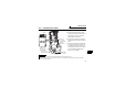
VECTOR CONTROL (2) Vector control dedicated motor (SF-V5RU), 12V complimentary (torque control) MCCB SF-V5RU A B C *1 Three-phase AC power supply Inverter MCCB Three-phase AC power supply Forward rotation start Reverse rotation start Contact input common Speed limit command 3 2 Frequency setting potentiometer 1/2W1kΩ 1 Torque command (+) ( 10V) (-) R/L1 S/L2 PC T/L3 External thermal CS(OH) relay input *2 SD STF FR-A7AP STR PA1 10 U V W E 2W1kΩ G1 G2 A B PB1 C PB2 D Differential PZ1 PZ2 F G
VECTOR CONTROL *1 *2 For the fan of the 7.5kW or less dedicated motor, the power supply is single phase. (200V/50Hz, 200 to 230V/ 60Hz) Assign OH (external thermal input) signal to the terminal CS. (Set "7" in CS(OH) Pr. 186 ) PC Connect a 2W1kΩ resistor between the terminal PC and CS (OH). Install the resistor pushing against the bottom part of the terminal block so as to avoid a contact with other cables.
VECTOR CONTROL 5.2 Terminals Terminal PA1 PA2 PB1 PB2 PZ1 PZ2 PG SD 32 Terminal Name Description Encoder A-phase signal input Encoder A-phase inverse signal input Encoder B-phase signal input Encoder B-phase inverse signal input A-, B- and Z-phase signals are input from the encoder. (For details of pulse signal, refer to page 15.) Encoder Z-phase signal input Encoder Z-phase inversion signal input Power supply (positive side) input Power supply ground Input power for the encoder power supply.
VECTOR CONTROL 5.3 Vector Control Extended Parameter List Fitting the FR-A7AP adds the following parameters for vector control. Refer to the inverter manual (applied) for details of parameter.
VECTOR CONTROL Parameter Number 465 466 467 468 469 470 471 472 473 474 475 476 477 478 479 480 481 482 483 484 485 486 487 34 Name First position feed amount lower 4 digits First position feed amount upper 4 digits Second position feed amount lower 4 digits Second position feed amount upper 4 digits Third position feed amount lower 4 digits Third position feed amount upper 4 digits Fourth position feed amount lower 4 digits Fourth position feed amount upper 4 digits Fifth position feed amount lower 4 dig
VECTOR CONTROL Parameter Number 488 489 490 491 492 493 494 802 823 833 840 841 842 843 844 845 846 847 848 853 873 Name Twelfth position feed amount upper 4 digits Thirteenth position feed amount lower 4 digits Thirteenth position feed amount upper 4 digits Fourteenth position feed amount lower 4 digits Fourteenth position feed amount upper 4 digits Fifteenth position feed amount lower 4 digits Fifteenth position feed amount upper 4 digits Pre-excitation selection Speed detection filter 1 Speed detection
VECTOR CONTROL 5.4 Specifications Speed control range Speed variation ratio Speed control Torque control Function *1 *2 36 1:1500 (both driving/regeneration *1) ±0.
REVISIONS *The manual number is given on the bottom left of the back cover. Print Date Sep.