INVERTER Plug-in option FR-A7AR FR-A7AR E kit INSTRUCTION MANUAL Relay output function PRE-OPERATION INSTRUCTIONS INSTALLATION AND WIRING (FR-A700/F700 SERIES) INSTALLATION AND WIRING (FR-E700 SERIES (E kit)) RELAY OUTPUT 1 2 3 4
Thank you for choosing this Mitsubishi Inverter plug-in option. This instruction manual gives handling information and precautions for use of this equipment. Incorrect handling might cause an unexpected fault. Before using the equipment, please read this manual carefully to use the equipment to its optimum. Please forward this manual to the end user.
2. Injury Prevention 3) Usage WARNING CAUTION • Apply only the voltage specified in the instruction manual to each terminal. Otherwise, burst, damage, etc. may occur. • Ensure that the cables are connected to the correct terminals. Otherwise, burst, damage, etc. may occur. • Always make sure that polarity is correct to prevent damage, etc. Otherwise, burst, damage may occur. • While power is on or for some time after power-off, do not touch the inverter as it is hot and you may get burnt. 3.
— CONTENTS — 1 PRE-OPERATION INSTRUCTIONS 1 1.1 Unpacking and Product Confirmation .............................................................................................1 1.2 1.3 Parts ....................................................................................................................................................3 Specifications.....................................................................................................................................4 1.1.1 1.1.
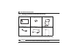
1 1.1 PRE-OPERATION INSTRUCTIONS Unpacking and Product Confirmation Take the plug-in option out of the package, check the product name, and confirm that the product is as you ordered and intact. This product is a plug-in option dedicated for the FR-A700/F700/E700 series. 1.1.1 Packing confirmation (FR-A700/F700 series) Check the enclosed items. Plug-in option Mounting screw (M3 × 6mm) Hex-head screw for option ......................................... 1 .............. 2 (Refer to page 6.) mounting (5.
PRE-OPERATION INSTRUCTIONS 1.1.2 Packing confirmation (FR-E700 series (E kit)) Check the enclosed items. Plug-in option ............................................... 1 Mounting screw (M3 × 6mm) Front cover for plug-in option ............ 2 (Refer to page 14, 17) ...............1(Refer to page 14, 17) Option protective cover *1 ...................... 1(Refer to page 14) Option small cover *2 Insulation sheet ................... 1(Refer to page 17) ...............
PRE-OPERATION INSTRUCTIONS 1.
PRE-OPERATION INSTRUCTIONS 1.3 Specifications (1) Types of output signal 1 changeover contact output (three relays are provided) (2) Contact capacity 230VAC .......... 0.3A 30VDC ............ 0.3A CAUTION • The contacts should be used within the rated capacity to prevent contacts weld resulting from faster contacts wearing.
2 INSTALLATION AND WIRING (FR-A700/F700 SERIES) 2.1 Pre-Installation Instructions Make sure that the input power of the inverter is off. CAUTION With input power on, do not install or remove the plug-in option. Otherwise, the inverter and plug-in option may be damaged. For prevention of damage due to static electricity, touch nearby metal before touching this product to eliminate static electricity from your body.
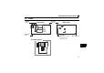
INSTALLATION AND WIRING (FR-A700/F700 SERIES) 2.2 Installation Procedure 1)Remove the inverter front cover. 1) 2)Mount the hex-head screw for option mounting into the inverter screw hole (on earth plate). (size 5.5mm, tightening torque 0.56N⋅m to 0.
INSTALLATION AND WIRING (FR-A700/F700 SERIES) CAUTION • • • When used with other plug-in options, always connect the FR-A7AR to the connector 1 to prevent malfunction. Only one type of option per inverter may be used. When two or more options are mounted, priority is in order of inverter option connectors 1, 2 and 3, the options having lower priority are inoperative. When the inverter cannot recognize that the option is mounted due to improper Mounting Error installation, etc.
INSTALLATION AND WIRING (FR-A700/F700 SERIES) 2.3 Wiring (1) Untwist the twisted pair shielded cables after stripping its sheath. Also, perform protective treatment of the shield to ensure that it will not make contact with the conductive area. Shield (perform protective treatment) Sheath Strip off the sheath about the size as in the right figure. If the length of the sheath pealed is too long, a short circuit may occur among neighboring wires. If the length is too short, wires might come off.
INSTALLATION AND WIRING (FR-A700/F700 SERIES) (2) Loosen the terminal screw and insert the cable into the terminal. Screw Size M3 Tightening Torque 0.5N⋅m to 0.6N⋅m Cable Size Screwdriver 0.3mm2 to 0.75mm2 Small flat-blade screwdriver (Tip thickness: 0.4mm/tip width: 2.5mm ) CAUTION • Undertightening can cause cable disconnection or malfunction. Overtightening can cause a short circuit or malfunction due to damage to the screw or unit.
INSTALLATION AND WIRING (FR-A700/F700 SERIES) (3) For wiring of the FR-A700 series 22K* or less and the FR-F700 series 30K* or less, route wires between the control circuit terminal block and front cover. If cables can not be routed between the control circuit terminal block and front cover due to the increased number of cables, remove a hook of the front cover and use a space become available.
INSTALLATION AND WIRING (FR-A700/F700 SERIES) REMARKS • When the hook of the inverter front cover is cut off for wiring, the protective structure (JEM1030) changes to open type (IP00). CAUTION When performing wiring using the space between the inverter front cover and control circuit terminal block, take care not to subject the cable to stress. After wiring, wire offcuts must not be left in the inverter. They may cause a fault, failure or malfunction.
3 INSTALLATION AND WIRING (FR-E700 SERIES (E kit)) 3.1 Pre-Installation Instructions Make sure that the input power of the inverter is off. CAUTION With input power on, do not install or remove the plug-in option. Otherwise, the inverter and plug-in option may be damaged. For prevention of damage due to static electricity, touch nearby metal before touching this product to eliminate static electricity from your body. 3.
INSTALLATION AND WIRING (FR-E700 SERIES (E kit)) z For FR-E720-3.7K (FR-E720-175) or less, FR-E740-7.5K (FR-E740-170) or less (1) Remove the front cover from the inverter. (For removing the front cover, refer to the FR-E700 series instruction manual.) (2) Remove the PU cover from the front cover. Open the PU cover with a driver, etc. and remove it in the direction of arrow as shown below. (1) Front cover * (2) PU cover * Open the PU cover, then open it toward the arrow direction to remove.
INSTALLATION AND WIRING (FR-E700 SERIES (E kit)) (3) Install the option protective cover. (4) Correctly install the insulating sheet between the inverter and plug-in option. (Refer to page 15 for installation method of an insulation sheet.) (5) Securely fit the connector of the plug-in option to the inverter connector along the guides. (6) Securely fix the both top and bottom of the plug-in option to the inverter with the accessory mounting screws.(tightening torque 0.45N⋅m to 0.
INSTALLATION AND WIRING (FR-E700 SERIES (E kit)) z Installation of an insulation sheet For FR-A7AR, put an insulation sheet under the screw platform of inverter (A of the following figure) and fit the insulation sheet to the screw position on the inverter side (B of the following figure). A B CAUTION • If an insulation sheet is not installed, the inverter and plug-in option may malfunction.
INSTALLATION AND WIRING (FR-E700 SERIES (E kit)) z For FR-E720-5.5K (FR-E720-240) or more, FR-E740-11K (FR-E740-230) or more (1) Remove the front cover 1 and 2 from the inverter. (For removing the front cover, refer to the FR-E700 series instruction manual.) (2) Remove the PU cover from the front cover 2. For removing the PU cover, refer to page 13. (3) Cut off the dummy cover of the front cover 1 with a nipper, etc. and make a space for installing the option small cover.
INSTALLATION AND WIRING (FR-E700 SERIES (E kit)) (4) Correctly install the insulating sheet between the inverter and plug-in option. (Refer to page 15 for installation method of an insulation sheet.) (5) Securely fit the connector of the plug-in option to the inverter connector along the guides. (6) Securely fix the both top and bottom of the plug-in option to the inverter with the accessory mounting screws. (tightening torque 0.45N⋅m to 0.
INSTALLATION AND WIRING (FR-E700 SERIES (E kit)) 3.3 Wiring (1) Untwist the twisted pair shielded cables after stripping its sheath. Also, perform protective treatment of the shield to ensure that it will not make contact with the conductive area. Shield (perform protective treatment) Sheath Strip off the sheath about the size as in the right figure. If the length of the sheath pealed is too long, a short circuit may occur among neighboring wires. If the length is too short, wires might come off.
INSTALLATION AND WIRING (FR-E700 SERIES (E kit)) (2) Loosen the terminal screw and insert the cable into the terminal. Screw Size Tightening Torque Cable Size Screwdriver M3 0.5N⋅m to 0.6N⋅m 0.3mm2 to 0.75mm2 Small flat-blade screwdriver (Tip thickness: 0.4mm/tip width: 2.5mm ) CAUTION • Undertightening can cause cable disconnection or malfunction. Overtightening can cause a short circuit or malfunction due to damage to the screw or unit.
INSTALLATION AND WIRING (FR-E700 SERIES (E kit)) (3) When wiring the FR-E700 series, if a hook of the front cover for the plug-in option impedes wiring, cut off the hook and perform wiring. Cut off with a nipper, etc. Cut off a hook at the bottom of the option cover. (Cut off so that no portion is left.
4 4.1 RELAY OUTPUT Internal Block Diagram You can select any three output signals (RUN, SU, FU, etc.) available with an inverter as standard, and output them as relay contact signals. Refer to page 23, 25 of the Instruction Manual (detailed) for details. The following is the internal block diagram of the FR-A7AR.
RELAY OUTPUT 4.
RELAY OUTPUT 4.4 Output Signal List (FR-A700/F700 series) For details of signal definitions, refer to Pr. 190 to Pr. 196 (Output terminal function selection) of the inverter (FR-A700/F700 series) manual.
RELAY OUTPUT Setting Signal Positive Name logic 47 64 70 71 72 73 74 75 76 77 78 84 *1 *2 *3 *4 PID During PID control activated Y64 During retry SLEEP PID output interruption Commercial-power supply side motor 1 RO1 connection RO1 *4 Commercial-power supply side motor 2 RO2 connection RO2 *4 Commercial-power supply side motor 3 RO3 connection RO3 *4 Commercial-power supply side motor 4 RO4 connection RO4 *4 RIO1 Inverter side motor 1 connection RIO1 *4 RIO2 Inverter side motor 2 connection RIO2 *4 RIO3 I
RELAY OUTPUT 4.5 Output Signal List (FR-E700 series) For details of signal definitions, refer to Pr. 190 to Pr. 192 (Output terminal function selection) of the inverter (FR-E700 series) manual.
RELAY OUTPUT 4.6 Connection Diagram When Using Electronic Bypass Sequence Function (FR-A700/F700 series) When using the electronic bypass sequence function with the FR-A7AR mounted to the FR-A700/F700 series inverter, it is recommended to use either connection shown below.
MEMO 27
REVISIONS *The manual number is given on the bottom left of the back cover. Print Date May, 2004 Dec., 2004 *Manual Number Revision IB(NA)-0600166ENG-A First edition IB(NA)-0600166ENG-B Partial modification Board shape change Addition Compatible with the FR-F700-NA series Sep., 2005 IB(NA)-0600166ENG-C Addition Compatible with the FR-A700 series Dec.