
Instruction manual


6
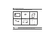
INSTALLATION AND WIRING (FR-A700/F700 SERIES)
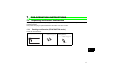
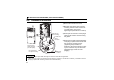
2.2 Installation Procedure
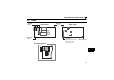
1)Remove the inverter front cover.
2)Mount the hex-head screw for option
mounting into the inverter screw hole
(on earth plate). (size 5.5mm,
tightening torque 0.56N⋅m to 0.75N⋅m)
3)Securely fit the connector of the plug-in
option to the inverter connector along
the guides.
4)Securely fix the both right and left sides
of the plug-in option to the inverter with
the accessory mounting screws.
(Tightening torque 0.45N⋅m to
0.55N⋅m) If the screw holes do not line-
up, the connector may not have been
plugged snugly. Check for loose
plugging.
REMARKS
• Remove a plug-in option after removing two screws on both left and right sides.
(When the plug-in option is mounted in the connector 3 (connector 1 for the FR-F
700 series), it is easier to remove
the plug-in option after removing a control circuit terminal block.)
4)
Mounting
screws
Inverter side
option
connector
Screw hole for
option mounting
Screw hole for
option mounting
(on earth plate)
Hex-head screw
for option mounting
1)
2)
3)