INVERTER INVERTER Plug-in option INVERTER FR-A7ND E kit IB(NA)-0600342ENG-C(1209) MEE Printed in Japan Specifications subject to change without notice.
Thank you for choosing this Mitsubishi Inverter plug-in option. This Instruction Manual gives handling information and precautions for use of this equipment. Incorrect handling might cause an unexpected fault. Before using the equipment, please read this manual carefully to use the equipment to its optimum. Please forward this manual to the end user.
2. Injury Prevention 3) Usage WARNING CAUTION • The voltage applied to each terminal must be the ones specified in the Instruction Manual. Otherwise burst, damage, etc. may occur. • The cables must be connected to the correct terminals. Otherwise burst, damage, etc. may occur. • Polarity must be correct. Otherwise burst, damage, etc. may occur. • While power is ON or for some time after power-OFF, do not touch the inverter as they will be extremely hot. Doing so can cause burns. 3.
⎯ CONTENTS ⎯ 1 PRE-OPERATION INSTRUCTIONS 1.1 Unpacking and Product Confirmation .............................................................................................1 1.1.1 1.1.2 1.2 1.3 1.4 2 2.1 2.2 2.3 3 3.1 3.2 4 4.1 4.2 1 SERIAL number.............................................................................................................................................. 1 Product confirmation........................................................................................
4.2.1 4.2.2 4.3 Operation Mode Setting ..................................................................................................................25 4.3.1 4.3.2 4.4 5 Operation selection at communication error occurrence (Pr. 500 to Pr. 502) .............................................. 34 Alarm and measures .................................................................................................................................... 38 Inverter Reset ....................................
7 OBJECT MAP 7.1 Class 0x01 (Identity-Object)............................................................................................................48 7.1.1 7.1.2 7.2 Class 0x2A Instance 1.................................................................................................................................. 70 Class 0x66 (Extended Object I).......................................................................................................79 7.8.1 7.9 Class 0x29 Instance 1 .......
.9.1 Class 0x67 Instance 1 .................................................................................................................................. 84 7.10 Class 0x70 to 0x79 (Extended Object III) .......................................................................................86 7.10.1 Class 0x70 to 0x79 Instance 1, 2 ................................................................................................................. 86 7.11 Class 0x80 (Extended Object IV) ................
1 PRE-OPERATION INSTRUCTIONS 1.1 Unpacking and Product Confirmation Take the plug-in option out of the package, check the product name, and confirm that the product is as you ordered and intact. This product is a plug-in option for the FR-E700 series inverter. 1.1.1 SERIAL number Check the SERIAL number indicated on the rating plate or package. For the 200V class of FR-E700, this option can be used with the inverter having the following SERIAL number or later.
PRE-OPERATION INSTRUCTIONS 1.1.2 Product confirmation Check the enclosed items. Plug-in option Mounting screw (M3 × 6mm) Terminal block .........................................................1 ........................ 2 (Refer to page 8, 10.) ......................... 1 (Refer to page 8, 10.) 78 23 23 78 901 456 901 456 X10 X1 Front cover for plug-in option Option protective cover Option small cover (Not used) .........................................................1 ..........................
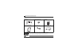
PRE-OPERATION INSTRUCTIONS 1.2 Parts Connector for communication Mount the accessory terminal block to connect to the network. MNS LED (operation status indication) Lit/flicker/off of the LED indicate inverter operation status. (Refer to page 4.) 78 78 456 X1 SW2 ON 456 SW1 X10 SHIELD 23 CAN- 901 1 2 23 V- 901 SW3 Front view Rear view LED1 2 1 MNS FR-A7ND Mounting hole 1 SW4 CAN+ V+ Mounting hole Mounting hole 1 2 ON Node address switch Set the node address.
PRE-OPERATION INSTRUCTIONS 1.3 MNS LED (operation status indication) The MNS LED indicates the operating status of the option unit by its indication status. Check the position of LED on page 3. LED Indication Operating Status Note · Turn inverter power on. Option unit will then complete duplicate Inverter power off station number test. Off Network power off · Check the voltage of the network power. Own node only on the network · Add other nodes to the network.
PRE-OPERATION INSTRUCTIONS 1.4 Specifications Item Specifications Control power Supplied from the inverter supply External power Input voltage: 11 to 28V input Consumption current: 90mA maximum Conforms to ODVA DeviceNet Specification Release 2.0 Standard (support UCMM) Network topology DeviceNet (linear bus with drop lines) Communication cable DeviceNet standard thick or thin cable (For a drop cable, use a thin cable.
2 INSTALLATION 2.1 Pre-Installation Instructions Make sure that the input power of the inverter is off. CAUTION Do not mount or remove the plug-in option while the power is being input. Otherwise, the inverter and plug-in option may be damaged. Static electricity in your body must be discharged before you touch the product. Otherwise the product may be damaged. 2.2 Installation Procedure The FR-E700 series has one connection connector for the plug-in option.
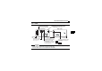
INSTALLATION z For FR-E720-3.7K (FR-E720-175) or lower and FR-E740-7.5K (FR-E740-170) or lower (1) Remove the front cover from the inverter. (For removing the front cover, refer to the FR-E700 instruction manual.) (2) Remove the PU cover from the front cover. Open the PU cover with a driver, etc. and remove it in the direction of arrow as shown below. (1) Front cover * 2 (2) PU cover * Open the PU cover, then open it toward the arrow direction to remove.
INSTALLATION (3) Install the option protective cover. (4) Securely fit the connector of the plug-in option to the inverter connector along the guides. (5) Securely fix the both top and bottom of the plug-in option to the inverter with the accessory mounting screws. (tightening torque 0.33N•m to 0.40N•m) If the screw holes do not line-up, the connector may not have been plugged snugly. Check for loose plugging.
INSTALLATION z For FR-E720-5.5K (FR-E720-240) or higher and FR-E740-11K (FR-E740-230) or higher (1) Remove the front cover 1 and 2 from the inverter. (For removing the front cover, refer to the FR-E700 instruction manual.) (2) Remove the PU cover from the front cover 2. For removing the PU cover, refer to page 7.
INSTALLATION (3) Install the front cover 1 to the inverter. (4) Securely fit the connector of the plug-in option to the inverter connector along the guides. (5) Securely fix the both top and bottom of the plug-in option to the inverter with the accessory mounting screws. (tightening torque 0.33N•m to 0.40N•m) If the screw holes do not line-up, the connector may not have been plugged snugly. Check for loose plugging.
INSTALLATION (4) Option connector of inverter Front cover 1 (3) Front cover for plug-in option (6) (8) Replace (5) Mounting screws 2 (7) Installation completed 11
INSTALLATION 2.3 Node Address Setting (1) Setting with node address switch Set the node address between "0 to 63" using node address switches on the FR-A7ND (refer to page 3). The setting is reflected when power turns on next or the inverter is reset. Set Pr. 345 or Class 0x03 Instance 1 Attribute 1 to "63 (initial value)". Set the arrow (×) of the corresponding switches to the number to set a desired address.
INSTALLATION (2) Set with parameter (Pr. 345) Use parameter (Pr. 345) of the inverter to set. Setting node address with parameter makes the node address setting invalid. The setting is reflected at the next power-on or inverter reset. (Refer to page 22) (3) Setting with master Use Class 0x03 Instance 1 Attribute 1 to set from the master. The setting change is reflected to Pr. 345. Setting node address from the master makes the node address switch setting invalid.
3 3.1 WIRING Connection to Network (1) Be sure to check the following before connecting the inverter to the network. · Check that the FR-A7ND is snugly inserted into the inverter. (Refer to page 6.) · Check that the correct node address is set. (Refer to page 12.) · Check that a drop cable is firmly connected to the FR-A7ND. (Refer to page 15.) (2) Make sure that the terminating resistor is installed at each end (between CAN+ and CAN-) of the trunk cable.
WIRING 3.2 Wiring (1) Strip the insulation back about 40mm on the free wire end of the drop cable to expose the four colored signal wires and the silver shield wire. (2) Strip the insulation back of each signal cable to use. If the length of the sheath pealed is too long, a short circuit may occur among neighboring wires. If the length is too short, wires might come off. Wire the stripped cable after twisting it to prevent it from becoming loose. (Do not solder it.
WIRING REMARKS Blade terminals available on the market (as of February 2012) zPhoenix Contact Co.,Ltd Terminal Screw Size Cable Size (mm 2) 0.3 to 0.5 0.5 to 0.75 M3 Blade Terminal Model With insulation Without insulation sleeve sleeve Al 0,5-6WH A 0,5-6 Al 0,75-6GY A 0,75-6 Crimping Tool Name CRIMPFOX 6 Insert wires to a blade terminal, and check that the wires come out for about 0 to 0.5 mm from a sleeve. Check the condition of the blade terminal after crimping.
WIRING (3) Loosen the terminal screw and insert the cable into the terminal according to the terminal arrignment. Tighten each cable with fixing screws to the recommended tightening torque. Screw Size Tightening Torque M3 0.5N•m to 0.6N•m Cable Size Screwdriver 0.3mm2 to Small flat-blade screwdriver (Tip thickness: 0.4mm/tip width: 2.5mm) 0.75mm 2 V- (black) CAN- (blue) Shielded cable CAN+ (white) V+ (red) Terminal layout CAUTION • Undertightening can cause cable disconnection or malfunction.
WIRING (5) When wiring the FR-E700 series, if a hook of the front cover of the plug-in option impedes wiring, cut off the hook and perform wiring. Cut off with a nipper, etc. Cut off a hook at the bottom of the option cover. (Cut off so that no portion is left.) REMARKS • 18 When the option protective cover is not fitted or wire is not passed through even if the hook of the front cover of the plug-in option has been cut off, the protective structure (JEM1030) changes to open type (IP00).
WIRING (6) For wiring of FR-E720-5.5K (FR-E720-240) or higher and FR-E740-11K (FR-E740-230) or higher, pass a cable on the inverter front cover as shown below. If a drop cable is passed through inside the inverter front cover, the bending radius of the cable becomes small, stressing the cable. 3 CAUTION When wiring, take care not to subject the cable to stress. After wiring, wire offcuts must not be left in the inverter. They may cause a fault, failure or malfunction.
4 INVERTER SETTING 4.1 Parameter List The following parameters are used for the communication option (FR-A7ND) Set the values according to need.
INVERTER SETTING 4.2 DeviceNet Data DeviceNet communication startup data can be set with the inverter parameter without using a DeviceNet configuration tool. For the setting method with a EDS file (refer to page 93) DeviceNet configuration tool, refer to the configuration tool manual.
INVERTER SETTING 4.2.1 DeviceNet address (Pr. 345) Parameter Number 345 Name DeviceNet address Setting Range Minimum Setting Increments Initial Value 0 to 4095 1 63 The definition of Pr. 345 is as follows.
INVERTER SETTING 4.2.2 DeviceNet baud rate (Pr. 346) Parameter Number 346 Name Setting Range Minimum Setting Increments Initial Value 0 to 4095 1 132 DeviceNet baud rate Set baud rate etc. to start DeviceNet communication.
INVERTER SETTING For Pr.346, determine its setting value according to the baud rate and output/input instances.
INVERTER SETTING 4.3 Operation Mode Setting The inverter mounted with a communication option has three operation modes. (1) PU operation [PU].............. Controls the inverter from the key of the operation panel on the inverter or parameter unit (FR-PU07/FR-PA07). (2) External operation [EXT] ... Controls the inverter by switching on/off external signals connected to the control circuit terminals of the inverter. (The inverter is factory-set to this mode.) (3) Network operation [NET] ...
INVERTER SETTING 4.3.2 Operation mode switching and communication startup mode (Pr. 79, Pr. 340) (1) Operation mode switching conditions Before switching the operation mode, check that: 1) The inverter is at a stop; 2) Both the STF and STR signals are off; and 3) The Pr. 79 Operation mode selection setting is correct. (Set using the operation panel of the inverter or parameter unit (FR-PU07/FR-PA07).) Refer to the Instruction Manual of the inverter for details of Pr. 79.
INVERTER SETTING Pr. 340 Setting Pr.
INVERTER SETTING (3) Operation mode switching method External operation When "0 or 1" is set in Pr. 340 Switching with the PU Switching through the network Switch to external operation mode through the network. Switch to network operation mode through the network. Press on the PU to light Press on the PU to light Network operation When "10" is set in Pr.
INVERTER SETTING 4.4 Operation and Speed Command Source (Pr. 338, Pr. 339, Pr. 550) (1) Select control source for the network operation mode (Pr. 550) A control location for the network operation mode can be selected from either the RS-485 communication with the PU connector or communication option. When using a communication option, set "0 or 9999 (initial value)" in Pr. 550.
INVERTER SETTING (2) Selection of control source for the network operation mode (Pr. 338, Pr. 339) ⋅ As control sources, there are the operation command source that controls the signals related to the inverter start command and function selection and the speed command source that controls the signals related to frequency setting. ⋅ In network operation mode, the commands from the external terminals and communication (PU connector or communication option) are as listed below. Operation Pr.
INVERTER SETTING Operation Pr. 338 Communication operation command source Location Pr. 339 Communication speed Selection command source OH 8 REX 15-speed selection 10 X10 Inverter run enable signal PU operation external X12 interlock X14 PID control valid terminal Brake opening completion BRI signal PU-External operation X16 switchover X18 V/F switchover Output stop Pr. 178 to Pr.
INVERTER SETTING Pr. 178 to Pr. 184 setting Selective function Operation Pr. 338 Communication operation command source Location Pr.
INVERTER SETTING 4.4.1 Communication EEPROM write selection (Pr. 342) When parameter write is performed from the communication option, write to RAM is enabled. Set when frequent parameter changes are necessary. Parameter Number 342 Name Communication EEPROM write selection Initial Value Setting Range 0 0 1 Description Parameter values written by communication are written to the EEPROM and RAM. Parameter values written by communication are written to the RAM.
INVERTER SETTING 4.5 Operation at Communication Error Occurrence 4.5.1 Operation selection at communication error occurrence (Pr. 500 to Pr. 502) You can select operations at communication error occurrences by setting Pr. 500 to Pr. 502 under network operation. (1) The set time from when a communication line error occurrence until communication error output You can set the waiting time from when a communication line error occurs until it is recognized as a communication error.
INVERTER SETTING (2) Display and erasure of communication error occurrence count The cumulative number of communication error occurrences can be indicated. Write "0" to erase this cumulative count.
INVERTER SETTING (3) Inverter operation selection at communication error occurrence You can select the inverter operation if a communication line error or an error of the option unit itself occurs. Parameter Number Name Setting Range Minimum Setting Increments Initial Value 502 Stop mode selection at communication error 0, 1, 2, 3 1 0 About setting z Operation at error occurrence Alarm Definition Pr.
INVERTER SETTING z Operation at error removal Alarm Definition Pr. 502 Setting Communication line 0 1 2 3 Communication option itself 0, 3 1, 2 Operation Indication Alarm Output Kept stopped E.OP1 kept lit Kept provided Restart Continued Normal indication Not provided Kept stopped E. 1 kept lit Kept provided CAUTION • A communication line error [E.OP1 (alarm data: HA1)] is an error that occurs on the communication line, and an error of the communication option unit itself [E.
INVERTER SETTING 4.5.2 Alarm and measures (1) The inverter operates as follows at alarm occurrences. Alarm Location Status Inverter operation Inverter Data communication Inverter operation Communication line Data communication Communication Inverter operation option connection Data communication Communication error option Inverter Error of operation communication Data option itself communication * Depends on the Pr. 502 setting.
INVERTER SETTING (2) Measures at alarm occurrences Alarm Indication Alarm Definition E.OP1 Communication line error E.1 Option alarm Measures Check the LED status of the option unit and remove the cause of the alarm. (Refer to page 4 for LED indication status) Inspect the master. Check the connection between the inverter and option unit for poor contact, etc. and remove the cause of the error.
INVERTER SETTING 4.6 Inverter Reset (1) Operation conditions of inverter reset Which resetting method is allowed or not allowed in each operation mode is described below. Resetting Method Inverter reset (Class 0x2A Instance 1 Attribute 101) Reset from the (Refer to page 72) *1 Pr.349 = 0 network Error reset at inverter fault (Refer to page 52) *2 Pr.
INVERTER SETTING (2) Error reset operation selection at inverter fault When used with the communication option, an error reset command* from network can be made invalid in the External operation mode or PU operation mode.
INVERTER SETTING 4.7 Frequency and Speed Conversion Specifications For frequency setting and monitoring from FR-A7ND, frequency is set in 0.01Hz increments and displayed on the monitor regardless of the Pr. 37 Speed display setting. Speed setting and monitor values from FR-A7ND are calculated by the following formula. Speed setting, monitor (1r/min increments) = frequency × 120 / number of motor poles (4*) * Calculated on the assumption that the number of motor poles is 4.
5 5.1 FUNCTIONS Output from the Inverter to the Network Main items to be output from the inverter (FR-A7ND) to the network and their descriptions are explained below. Item Inverter monitor Operation mode read Parameter read Inverter status Alarm definition Description Monitor various items such as inverter output frequency and output current. Read the operation mode of the inverter. Read parameter settings of the inverter. Monitor the output signal of the inverter.
6 OBJECT MAP DEFINITIONS 6.1 Object Model of DeviceNet Communication For DeviceNet communication, each node is modeled as collections of objects (abstraction of particular functions of the products). The following four terms are used to describe object. Item Class Instance Attribute Service Description Collections of all objects which have same types of functions.
OBJECT MAP DEFINITIONS 6.2 Response Level 6.2.
OBJECT MAP DEFINITIONS 6.2.2 Response level of explicit message (1) Reading Request Response Within 50ms (2) Writing Request Response Within 50ms (3) Parameter clearing The inverter will not respond until parameter clear processing complete (about 5s) after sending parameter all clear command.
OBJECT MAP DEFINITIONS 6.3 Recommendation for Software Developers Please note the followings when developing designing. (1) After sending request to the FR-A7ND, wait for response from the FR-A7ND, then send the next request. (2) Set waiting time between each message based on FR-A7ND response time on page 45. For example, after sending a writing request by Explicit message, wait for more than 50ms, then send the next request.
7 OBJECT MAP 7.1 Class 0x01 (Identity-Object) 7.1.
OBJECT MAP 7.1.2 Class 0x01 Instance 1 (1) Attribute *1 *2 *3 Attribute ID Access 1 2 3 4 5 Get Get Get Get Get Data Length Description Attribute Value Vendor ID (Mitsubishi electric) Device Type (AC drive) Product Code Revision Status Word 161 Word 02 Word 49 Struct 1.YYY *1 *2 Word Double 6 Get Serial Number xxxxxxxx Word 7 Get Product Name (FR-E700) 5 Byte E700 *3 High byte of hexadecimal word data means integer and low byte means decimal.
OBJECT MAP 7.2 Class 0x03 (DeviceNet Object) 7.2.1 Class 0x03 Instance 1 (1) Attribute Attribute ID Access 1 Get/Set MAC ID *1 Name Initial Value *2 2 Get/Set Baud Rate *1 00 Description 00 to 63: Node address value 00: 125kbps, 01: 250kbps, 02: 500kbps Allocation Information 5 Get Allocation Choice Byte Master's MAC ID 8 *1 *2 Get MAC ID Switch Value 00 0: G2Explicit, 1: Poll, 2: Bit Strobe, 3: Multicast Poll, 4: Change Of State, 5: Cyclic 0 to 63, 255: Changed with Allocate only.
OBJECT MAP 7.3 Class 0x04 (Assembly Object) Attribute ID Access Name 3 Get Data Initial Value Data Length ⎯ Description Byte alignment Refer to page 52 or later. Set I/O instance in either of the following methods. y Pr.346 setting (Refer to page 23) y Class 0x29, Instance 1, Attribute 140, 141 setting (Refer to page 69) Output Instance Input Instance Refer to page 20 (4 byte) 21 (4 byte) 126 (6 byte) 70 (4 byte) 71 (4 byte) 176 (6 byte) 52 54 56 * Value in parenthesis is data length.
OBJECT MAP 7.3.1 Output Instance 20/Input Instance 70 1. Output Instance 20 (Master→inverter) When using Output Instance 20, set Input Instance to 70.
OBJECT MAP 2. Input Instance 70 (Inverter→master) When using Input Instance 70, set Output Instance to 20.
OBJECT MAP 7.3.2 Output Instance 21/Input Instance 71 1. Output Instance 21 (initial value) (Master→inverter) When using Output Instance 21, set Input Instance to 71.
OBJECT MAP 2. Input Instance 71 (initial value) (Inverter→master) When using Input Instance 71, set Output Instance to 21.
OBJECT MAP 7.3.3 Output Instance 126/Input Instance 176 1. Output Instance 126 (Master→inverter) When using Output Instance 126, set Input Instance to 176. Byte Bit7 0 Write Param 1 2 3 4 5 56 Bit6 Net Ref Bit5 Net Ctrl Bit4 ⎯ Bit3 Bit2 Bit1 Bit0 ⎯ Fault Reset Run Rev Run Fwd Parameter Instance No.
OBJECT MAP [Output Instance 126 details] Byte0 Bit0 Bit1 Run Fwd Run Rev Bit2 Fault Reset Bit5 NetCtrl Bit6 NetRef Bit7 Write Param Byte1 Byte2 Byte3 Byte4 Byte5 Parameter Instance No.
OBJECT MAP 2. Input Instance 176 (Inverter→master) When Input Instance 176 is used, 16 bit parameter data is provided. When using Input Instance 176, set Output Instance to 126.
OBJECT MAP [Input Instance 176 details] Bit0 Faulted Bit2 Bit3 Run Command Mode * Running Fwd Running Rev Bit4 Ready Bit5 CtrlFromNet Bit6 RefFromNet Bit7 AtReference Bit7 PrEnd Bit1 Byte0 Byte1 Byte2 Byte3 Byte4 Byte5 Speed Actual Parameter Read Data Inverter error signal (0: inverter is under normal operation, 1: inverter is in a fault state) 0: Command is disabled in network operation 1: Command is enabled in network operation Forward rotation (0: other than forward rotation, 1: forward
OBJECT MAP 7.4 Class 0x05 (DeviceNet Connection Object) FR-A7ND supports only Polling I/O and Explicit message, not Bit-Strobed I/O. In addition, Instance 4 to 6 are Explicit message Instance. 7.4.
OBJECT MAP Class 0x05 Instance 1 Attribute ID Access 8 Get 9 Get/Set 12 Get/Set 13 Get 14 Get 15 Get 16 Get Name Range Consumed Connection Size 0 to 0xFFFF Expected Pack Rate (EPR) 0 to 0xFFFF Watchdog Action Produced Connection Path Length Produced Connection Path Consumed Connection Path Length Consumed Connection Path 00 01 02 03 0 to 0xFFFF Variable 0 Variable Definition This value specifies the maximum number of Message Body bytes that a module is able to receive across the connec
OBJECT MAP 7.4.
OBJECT MAP Class 0x05 Instance 2 Attribute ID Access *1 Name 9 Get/Set Expected Packet Rate (EPR) 12 Get/Set Watchdog Action 13 Get Produced Connection Path Length 14 Get Produced Connection Path 15 Get Consumed Connection Path Length 16 Get Consumed Connection Path Range Definition 0 to 0xFFFF (Example) 2500: 2500ms 0 1 2 Transition to time out (initial value) Auto Delete Auto reset Specifies the number of bytes of information within the 0 to 0xFFFF produced_connection_path attribur
OBJECT MAP (Example) When Output Instance 21 and Input Instance 71 are used as sent and receive data (a) Produced Connection Path (send data) Input Instance 71 = 0x47 ASCII code: 4 = 034, 7 = 037 Therefore, Produced Connection Path = 0x62 0x34 0x37 For changing Input Output Assembly, refer to page 68.
OBJECT MAP 7.4.
OBJECT MAP Class 0x05 Instance 4, 5, 6 Attribute ID Access 7.4.4 9 Get/Set 12 Get/Set Watchdog Action 13 Get 14 Get 15 Get 16 Get Produced Connection Path Length Produced Connection Path Consumed Connection Path Length Consumed Connection Path Range 0 to 0xFFFF 00 01 02 03 0 to 0xFFFF Variable 0 Variable Definition (Example) 2500: 2500ms Invalid Auto Delete (Initial value) Invalid Deferred Delete Specifies the number of bytes of information within the produced_connection_path attriburte.
OBJECT MAP 7.5 Class 0x28 (Motor Data Object) 7.5.1 Class 0x28 Instance 1 (1) Attribute Attribute ID Access 3 Get/Set Motor type 6 Get/Set Rated motor current (Pr. 9) 7 Get/Set Name Rated voltage (Pr. 19) Range Description 7 Squirrel-cage induction motor (fixed value) 0 to 0xFFFF [GET] Return the Pr. 9 setting in 0.1A increments. [SET] Write the value to Pr. 9 in 0.1A increments. 0 to 0xFFFF [GET] · When Pr.
OBJECT MAP 7.6 Class 0x29 (Control Supervisor Object) 7.6.1 Class 0x29 Instance 1 (1) Attribute Class 0x29 Instance 1 Attribute ID Access Name Initial Value 3 Get/Set RUN1 00 4 Get/Set RUN2 00 5 Get/Set NetCtrl (operation command source) (Pr. 338) Range Description 0 1 0 1 5 6 7 0 Stop Forward rotation Stop Reverse rotation Other than DeviceNet Actual state of communication operation operation command DeviceNet communication can be monitored with Attribute 15.
OBJECT MAP Class 0x29 Instance 1 Attribute ID Access Initial Value Range Description During reset or alarm occurrence Stop or running No fault present 10 Get Faulted 0 Fault occurred (latched) Reset release at fault occurrence FaultRst 12 Get/Set 0 (fault reset) *1 Reset execution at fault occurrence Other than DeviceNet communication CtrlFromNet 0 operation 15 Get (operation command 1 source monitor) *2 1 DeviceNet communication operation 0x46 Input Instance 70 Instance ID of Input 0x47 140 Get/Set 0x4
OBJECT MAP 7.7 Class 0x2A (AC Drive Object) 7.7.1 Class 0x2A Instance 1 (1) Attribute Class 0x2A Instance 1 Attribute Access ID 3 4 AtReference (up to frequency) NetRef Get/Set (operation command source) (Pr.
OBJECT MAP Class 0x2A Instance 1 Attribute Access ID 9 Get 15 Get 17 Get 18 Get/Set 19 Get/Set 20 Get/Set 21 Get/Set 29 Get Name CurrentActual (actual current) PowerActual (actual power) OutputVoltage (output voltage) Range Description 0 to 3276.7A The output current is monitored in 0.1A increments. 0 to 65535W Output power is monitored in 1W increments. The output voltage is monitored in 1V increments. Acceleration time = Pr. 7 × (Pr. 1 / Pr.
OBJECT MAP Class 0x2A Instance 1 Attribute Access Range ID Description 101 Set 102 103 Set Set Inverter reset Set a value other than "0" in Pr. 340 to start in network operation mode after reset. (Refer to page 26) *1 0x965A Parameter clear *1 0x99AA All parameter clear *1 105 Set 0x5A96 106 Set 0xAA99 All parameter clear *1 Any Clear parameters *1 Communication parameters are not cleared. *3 0 to Either write the set frequency to RAM or read Set frequency (RAM) *2 0x9C40 from RAM. (0.
OBJECT MAP Class 0x2A Instance 1 Attribute Access Range ID * ⎯ 0 1 2 3 4 5 0x0010 0x0011 0x0014 114 Get/Set 120 Get/Set 141 Get/Set ⎯ 142 143 144 145 146 147 148 Get Get Get Get Get Get Get ⎯ ⎯ ⎯ ⎯ ⎯ ⎯ ⎯ Description Inverter status monitor/run command (Refer to page 74) External operation PU operation External jog operation Operation mode read (Get) PU jog operation Network operation External/PU combined operation External operation Operation mode write (Set) PU operation (when Pr.
OBJECT MAP Bit map of inverter status monitor/running command is as follows. z Inverter status monitor (Get) Bit Signal 0 Running (RUN signal) 1 During forward rotation 2 During reverse rotation 3 4 5 Up to frequency (SU signal) Overload alarm (OL signal) ⎯ (Not used) 6 Frequency detection (FU signal) 7 Alarm (ALM signal) 8 to 14 ⎯ (Not used) 15 74 Inverter operation ready (RY signal) Description 1 : Inverter output frequency reaches or exceeds Pr.13 Starting frequency.
OBJECT MAP z Run command (Set) Bit Signal 0 ⎯ (Not used) 1 Forward rotation command *2 2 Reverse rotation command *2 High speed operation command (terminal RH function) *1 Middle speed operation command 4 (terminal RM function) *1 Low speed operation command 5 (terminal RL function) *1 6 ⎯ (Not used) Second function selection 7 (RT signal) *3 Terminal 4 input selection 8 (AU signal) *3 9 ⎯ (Not used) Output stop 10 (terminal MRS function) *1 11 ⎯ (Not used) 12 Reset (terminal RES function) *1 13 to
OBJECT MAP *1 *2 *3 76 Signal names are initial values. Using Pr. 180 to Pr .184, you can change input signal functions. Note that some of signals do not accept a command from the network according to the Pr. 338 and Pr. 339 settings. For example, reset (terminal RES function) of Bit12 can not be controlled via the network. (refer to page 30) Refer to the Instruction Manual of the inverter for details of Pr. 180 to Pr.184. Signals of the Bit1 and Bit2 can not be changed.
OBJECT MAP zList of alarm definition Refer to the Instruction Manual of the inverter for details of alarm definitions. Data 0x00 0x10 0x11 0x12 0x20 0x21 0x22 0x30 0x31 0x40 0x52 0x60 0x70 0x80 0x81 0x90 0xA0 Definition No alarm E.OC1 E.OC2 E.OC3 E.OV1 E.OV2 E.OV3 E.THT E.THM E.FIN E.ILF E.OLT E.BE E.GF E.LF E.OHT E.OPT Data 0xA1 0xB0 0xB1 0xB2 0xB3 0xC0 0xC5 0xC7 0xC8 0xD8 0xD9 0xDA 0xDB 0xF1 0xF6 0xF7 0xFD Definition E.OP1 E.PE E.PUE E.RET E.PE2 E.CPU E.IOH E.AIE E.USB E.MB4 E.MB5 E.MB6 E.MB7 E.1 E.
OBJECT MAP Class 0x2A Instance 1 Attribute ID Access *1 170 171 172 174 176 Get Get Get Get Get 177 Get 178 Get 179 Get Attribute ID Access Description (Increments) Output frequency (0.01Hz) Output current (0.01A) Output voltage (0.1V) Frequency setting (0.01Hz) Motor torque (0.1%) Converter output voltage (0.1V) Regenerative brake duty (0.1%) Electronic thermal relay function load factor (0.
OBJECT MAP 7.8 Class 0x66 (Extended Object I) 7.8.1 Class 0x66 Instance 1 Set parameters of the inverter. Refer to the Instruction Manual of the inverter for details of the parameters. REMARKS • When reading/writing parameter, Class 0x70 to 0x79 (Extended object III) is recommended. (Refer to page 86) (1) Attribute Class 0x66 Instance 1 Attribute ID Parameters Access 10 Pr. 0 Get/Set 11 Pr. 1 Get/Set 12 Pr. 2 Get/Set 13 Pr. 3 Get/Set 14 Pr. 4 Get/Set 15 Pr. 5 Get/Set 16 17 18 19 Pr. 6 Pr. 7 Pr.
OBJECT MAP Class 0x66 Instance 1 Attribute ID Parameters Access Name 36 Pr. 26 Get/Set Multi-speed setting (speed 6) 37 Pr. 27 Get/Set Multi-speed setting (speed 7) Acceleration/deceleration 39 Pr. 29 Get/Set pattern selection 40 Pr. 30 Get/Set Regenerative function selection 41 Pr. 31 Get/Set Frequency jump 1A 42 Pr. 32 Get/Set Frequency jump 1B 43 Pr. 33 Get/Set Frequency jump 2A 44 Pr. 34 Get/Set Frequency jump 2B 45 Pr. 35 Get/Set Frequency jump 3A 46 Pr. 36 Get/Set Frequency jump 3B 47 Pr.
OBJECT MAP Class 0x66 Instance 1 Attribute ID Parameters Access 85 Pr. 75 Get/Set 87 Pr. 77 Get 88 Pr. 78 Get/Set 89 90 91 92 93 94 Pr. 79 Pr. 80 Pr. 81 Pr. 82 Pr. 83 Pr. 84 Get Get/Set Get/Set Get/Set Get/Set Get/Set 99 Pr. 89 Get/Set 100 101 102 103 104 106 Pr. 90 Pr. 91 Pr. 92 Pr. 93 Pr. 94 Pr. 96 Get/Set Get/Set Get/Set Get/Set Get/Set Get/Set 127 Pr. 117 Get/Set 128 Pr. 118 Get/Set 129 Pr. 119 Get/Set 130 Pr.
OBJECT MAP Class 0x66 Instance 1 Attribute ID Parameters Access 82 161 Pr. 151 Get/Set 162 163 Pr. 152 Pr. 153 Get/Set Get/Set 166 Pr. 156 Get/Set 167 170 Pr. 157 Pr. 160 Get/Set Get/Set 171 Pr. 161 Get/Set 172 Pr. 162 Get/Set 175 Pr. 165 Get/Set 178 179 180 181 Pr. 168 Pr. 169 Pr. 170 Pr. 171 182 Pr. 172 183 184 188 189 190 191 Pr. 173 Pr. 174 Pr. 178 Pr. 179 Pr. 180 Pr.
OBJECT MAP Class 0x66 Instance 1 Attribute ID Parameters Access 231 Pr. 251 Get/Set 235 Pr. 255 Get 236 Pr. 256 Get 237 Pr. 257 Get 238 Pr. 258 Get 239 Pr. 259 Get 241 247 Pr. 261 Pr. 267 Get/Set Get/Set 248 Pr. 268 Get/Set 249 Pr.
OBJECT MAP 7.9 Class 0x67 (Extended Object II) 7.9.1 Class 0x67 Instance 1 Set parameters of the inverter. Refer to the Instruction Manual of the inverter for details of the parameters. REMARKS • When reading/writing parameter, Class 0x70 to 0x79 (Extended object III) is recommended. (Refer to page 86) (1) Attribute Attribute ID Parameters Access 84 Name Attribute ID Parameters Access Name 38 Pr. 338 Communication operation Get/Set command source 39 Pr.
OBJECT MAP Attribute ID Parameters Access Name 202 C2 Terminal 2 frequency setting Get/Set bias frequency (Pr. 902) 203 C3 Terminal 2 frequency setting Get/Set bias (Pr. 902) 204 Pr. 125 Terminal 2 frequency setting Get/Set gain frequency (Pr. 903) 205 C4 Terminal 2 frequency setting Get/Set gain (Pr. 903) 206 C5 Terminal 4 frequency setting Get/Set bias frequency (Pr. 904) 207 C6 Terminal 4 frequency setting Get/Set bias (Pr. 904) 208 Pr.
OBJECT MAP 7.10 Class 0x70 to 0x79 (Extended Object III) 7.10.1 Class 0x70 to 0x79 Instance 1, 2 Set parameters of the inverter. Refer to the Instruction Manual of the inverter for details of the parameters. (1) Attribute Class Instance Attribute Parameters Access Description 0x70 0x71 0x72 0x73 0x74 0x75 0x76 0x77 0x78 1 1 1 1 1 1 1 1 1 1 2 10 to 109 10 to 109 10 to 109 10 to 109 10 to 109 10 to 109 10 to 109 10 to 109 10 to 109 10 to 109 10 to 49 Pr. 0 to Pr. 99 Pr. 100 to Pr. 199 Pr.
OBJECT MAP 7.11 Class 0x80 (Extended Object IV) 7.11.1 Class 0x80 Instance 1 Inverter monitored value can be read. Refer to the Instruction Manual of the inverter for details of each monitor. (1) Attribute Attribute ID Access Description (Increments) 11 12 13 15 17 18 19 Get Get Get Get Get Get Get 20 Get 21 Get 22 Get 24 Get Output frequency (0.01Hz) Output current (0.01A) Output voltage (0.1V) Frequency setting (0.01Hz) Motor torque (0.1%) Converter output voltage (0.
OBJECT MAP (2) Service Service Code 0x0E 88 Description Get Attribute Single
OBJECT MAP 7.12 FR-E5ND (FR-E500-KND) Compatible Mode Switching to the FR-E5ND (FR-E500-KND) compatible mode enables DeviceNet communication with the FR-E5ND (FR-E500-KND) specifications.
OBJECT MAP (2) Specification of the FR-E5ND (FR-E500-KND) compatible mode The table below shows the differences between the FR-E5ND (FR-E500-KND) compatible mode and the normal mode. Refer to the FR-E5ND and FR-E500-KND manuals for details of each function of compatible mode Class ID Instance Attribute ID ID Name 0x03 1 1 0x28 1 6 Node address setting (MAC ID) Rated current (Pr.9) 0x28 1 7 Rated voltage 0x28 0x28 1 1 9 15 0x2A 1 7 Rated frequency (Pr.84) Base speed (Pr.
OBJECT MAP Class ID Instance Attribute ID ID 0x2A 1 9 0x2A 1 17 0x2A 1 18 0x2A 1 19 0x2A 1 114 Name CurrentActual (actual current) OutputVoltage (output voltage) AccelTime (acceleration time) DecelTime (deceleration time) Run command (Set) FR-E5ND (FR-E500-KND) Compatible Mode Normal Mode (FR-A7ND) 0.01A increments 0.1A increments 0.1V increments 1V increments Period of time from 0 to reach Pr.20 Acceleration/deceleration reference frequency (Pr.7, Pr.8) 0.
8 TROUBLESHOOTING If a fault occurs and the inverter fails to operate properly, locate the cause of the fault and take proper corrective action by referring to the troubleshooting below. If the corresponding information is not found in the table, the inverter has problem, or the component parts are damaged, contact your sales representative. Display Operation LED of panel of FR-A7ND inverter E.OP1 0.
APPENDIX EDS File EDS file can be downloaded from the web site. Download the EDS file that supports the mode to be used (normal mode / FR-E5ND (FR-E500-KND) compatible mode). (Refer to page 89 for the mode switchover.) Mitsubishi Electric FA Site http://www.MitsubishiElectric.co.jp/fa/ The download is free. Contact your sales representative for details. REMARKS • The EDS file has been constructed to ODVA standards on condition that a configuration software is used.
APPENDIX Error Code List Error Code Name 0x00 Success 0x02 Resource unavailable 0x04 Path segment error 0x05 Path destination unknown 0x07 Connection lost 0x08 Service not supported 0x09 Invalid attribute value 0x0A Attribute list error 0x0C 0x0D 0x0E 0x0F Already in requested mode/ state Object state conflict Object already exist Attribute not settable Privilege violation 0x10 Device state conflict 0x0B 94 Description Service was successfully performed by the object specified.
APPENDIX Error Code Name 0x11 Reply data too large 0x13 0x14 0x15 0x16 0x18 Not enough data Attribute not supported Too much data Object does not exist No stored attribute data 0x19 Store operation failure 0x1C Missing attribute list entry data 0x1D Invalid attribute value list 0x1F 0x20 0x27 Vender specific error Invalid parameter Unexpected attribute in list 0x28 Invalid Member ID 0x29 Member not settable 0x2A Group 2 only server general failure Description The data to be transmitted i
REVISIONS *The manual number is given on the bottom left of the back cover. Print Date *Manual Number Revision Dec. 2007 IB(NA)-0600342ENG-A First edition IB(NA)-0600342ENG-B Addition Sep. 2012 IB(NA)-0600342ENG-C Dec.
INVERTER INVERTER Plug-in option INVERTER FR-A7ND E kit IB(NA)-0600342ENG-C(1209) MEE Printed in Japan Specifications subject to change without notice.