
Specifications


3
PRE-OPERATION INSTRUCTIONS
1
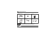
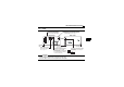
1.2 Parts
CAUTION
• Set the compatible mode switch (SW3) before switching ON the inverter and do not change the setting
while the power is ON. Otherwise you may get an electric shock.
• Do not turn ON the switch 2 of the compatible mode switch (SW3).
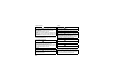
Front view Rear view
LED1
2
1
0
9
8
7
6
5
4
3
2
1
0
9
8
7
6
5
4
3
2
1
X10 X1
SW3
SW1
SW2
SW4
V-
CAN-
SHIELD
CAN+
V+
SW4
O
N
2
L
ON
12
ON
12
Mounting
hole
MNS LED (operation status indication)
Lit/flicker/off of the LED indicate inverter
operation status.
Connector
Connect to the inverter
option connector.
Compatible mode switch (
SW3)
Switch over to the FR-E5ND
(FR-E500-KND) compatible mode.
(In the initial status, the switches
1 and 2 are both OFF.)
Node address switch
Set the node address.
Mounting hole
Connector for communication
Mount the accessory terminal
block to connect to the network.
FR-A7ND
MNS
Mounting
hole
Switch for manufacturer setting
Do not change from initially-set
status (OFF).
(Refer to page 4.)
(Refer to page 12.)
(Refer to page 89.)