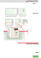
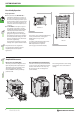
MITSUBISHI ELECTRIC Frequency Inverter 150 138 6 2x ø5 5 208 6 6 FR-E 500 EC 73 64 6 11 148 220 6 2x ø5 5 6 208 150 RUN STOP RESET 6 138 45 68 A1 6 61 11 A 220 Hz RUN A MON PU EXT RUN STOP RESET Technical Catalogue 2005
FR-E 500 EC Frequency Inverters ct The Compa r All-Rounde With the FR-E500 series frequency inverters MITSUBISHI ELECTRIC offers high-tech equipment at particular compact dimensions. These frequency inverters are designed especially for low to medium capacity drive tasks. The inverters are available for a performance range of 0.4 to 2.2 kW (1 phase) and 0.4 to 7.5 kW (3 phase).
CONTENTS FREQUENCY INVERTER FR-E 500 EC SYSTEM DESCRIPTION 웇 웇 웇 웇 웇 Introduction of the FR-E series . . . . . . . . . . . . . . . . . . . . . . . . . . . . . . . . . . . . . . . . . . . . . . . . . . . . . . . . . . . . . . . . . . . . . . . . . . . . . 4 Speed/torque characteristics . . . . . . . . . . . . . . . . . . . . . . . . . . . . . . . . . . . . . . . . . . . . . . . . . . . . . . . . . . . . . . . . . . . . . . . . . . . . . . 5 Equipment and configuration. . . . . . . . . . . . . . . . . . . .
SYSTEM DESCRIPTION The Frequency Inverter FR-E 500 EC Due to its versatility and compact dimensions the FR-E 500 EC is a frequency inverter solving most effectively your individual drive tasks. Its extensive functions allow flexible applications. The outstanding drive features of the FR-E 500 EC suits various needs: The inverters are available for a performance range of 0.4 to 2.2 kW (1 phase) and of 0.4 to 7.5 kW (3 phase). The output frequency ranges from 0.2 to 400 Hz.
SYSTEM DESCRIPTION Optimised Drive Characteristics Advanced flux vector control The original flux vector control developed by MITSUBISHI ELECTRIC offers new performance characteristics in drive technology. Flux vector control (slip compensation selected) 300 By combining slip compensation and flux vector control MITSUBISHI ELECTRIC has achieved a loaded torque of 150 % at a frequency of 1 Hz.
SYSTEM DESCRIPTION User-friendly Operation Easy operation 앬 The parameter unit FR-PA02-02 is available for all frequency inverters. It provides a clear and easy operation of the inverter and displays several operational and alarm signals. The parameter unit can be connected remotely via an extension cable and an adapter (see accessories). 앬 The FR-PU04 control panel is optionally available. It provides a long-life backlight LC display. Operational data is directly input via the numeric keypad.
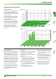
SYSTEM DESCRIPTION Environmentally Friendly Operation Soft-PWM control With Soft-PWM control Noise level In addition to the conventional low-noise mode, MITSUBISHI ELECTRIC has developed its original Soft-PWM control that suppresses acoustic noise and limits RFI noise to a minimum. The switchable PWM control facilitates a motor noise as silent as whisper even at low carrier frequencies. The diagrams illustrate the difference.
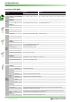
SYSTEM DESCRIPTION Specifications FR-E 500 EC FR-E 520S EC Product line 0.4 k 150%Overloadcapacity 0.75 Ratedmotor capacity[kW] 200%Overloadcapacity 0.4 Rated current [A] Output Input 0.4 k 0.75 k 1.5 k 2.2 k 3.7k 5.5 k 7.5 k 1.1 2.2 3 0.75 1.1 2.2 3 4 7.5 11 1.5 2.2 0.4 0.75 1.5 2.2 4 5.5 7.5 5 9.6 12 1.8 3 4.9 6.7 9.5 14 21 200%Overloadcapacity 2.5 4 7 10 1.6 (1.4) 2.6 (2.2) 4 (3.8) 6 (5.4) 9.5 (8.7) 12 17 1.5 2.7 3.8 1.2 2.0 3.0 4.6 7.
SYSTEM DESCRIPTION FR-E 520S EC Product line Display option Protection Others 0.4 k 0.75k FR-E 540 EC 1.5 k 2.2 k 0.4 k 0.75 k 1.5 k 2.2 k Displayed on control panel (FR-PU04/ FR-PA02-02) Operating state Outputfrequency,motorcurrent,outputvoltage,frequencysettingvalue,operationspeed Alarm display Error messages are displayed after a protective function is activated. Up to 4 error codes can be stored.
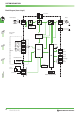
SYSTEM DESCRIPTION Block Diagram (Source Logic) P1 + PR Converter Power supply* Motor L1 L2 L3 U V W Voltage supply Input signal circuits Protective functions PC STF STR RH RM RL MRS RES SD Reset ALARM CPU LSI A B C Error output AM 5 Analog output SE RUN FU Operating state output Parameter unit PU/PA Options 1kΩ/2W 0–5 V 0–10 V 0/4–20 mA 10 2 5 4 LED/LC display PU/PA 10 FR-E 500 EC MITSUBISHI ELECTRIC
SYSTEM DESCRIPTION Terminal Assignment of Signal Terminals Function Control connection Terminal STF Forward rotation start The motor rotates forward, if a signal is applied to terminal STF. STR Reverse rotation start The motor rotates reverse, if a signal is applied to terminal STR. RH, RM, RL Multi-speed selection Preset of 15 different output frequencies; programmable. MRS Output stop The signal stops the output frequency without regard to the delay time; programmable.
CONTROL PANELS Parameter Unit FR-PA02-02 (optional) The parameter unit FR-PA02-02 is the standard control device for the frequency inverter FR-E 500 EC. It fulfils the major tasks for operating the inverter achieving a particular cost effectiveness. The parameter unit supports the input and display of several control variables (parameters) and monitores and indicates current operational data. The data is displayed on a 4-digit LED display.
CONTROL PANELS Parameter Unit FR-PU04 (optional) The parameter unit FR-PU04 including extended functions is available as optional accessory. It provides a 10-key keypad for entering directly numerical values. A 4-row LC display returns operational data, parameter names or status and error messages in uncoded text. The parameter unit displays text in the following selectable languages: English, German, French, Spanish, Swedish, Italian, Finnish, and Japanese.
CONTROL PANELS Operating Modes The inverter can alternatively be operated via external signals or directly via the parameter units FR-PA02-02 or FR-DU04. A combined operation is possible too. The operating mode on the parameter unit FR-PA02-02 is selected within the operation mode menu. With the parameter unit FR-PU04 the selection is done by pressing the EXT OP key for external signal operation and PU OP for control panel operation.
CONTROL PANELS VFD Setup Software The VFD Setup Software is a powerful tool for the operation of your frequency inverter. The software (version 2.4) is MS Windows 95/98/XP and NT/2000 compatible, and therefore allows the inverter operation via any conventional personal computer. Several frequency inverters can be set up, operated, and monitored simultaneously across a network or via a personal computer or notebook.
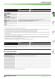
PARAMETER Overview of Parameters Function Parameter Basic parameters Parameters for standard drive operation Settings of control outputs 2nd parameter settings Display functions Default setting Torque boost (manual) 0–30 % 6%/4% 1 Maximum output frequency 0–120 Hz 120 Hz 2 Minimum output frequency 0–120 Hz 0 Hz Aux. function Meaning 3 V/f characteristics (base frequency) 0–400 Hz 50 Hz 4 1. Multispeed (high) preset - RH 0–400 Hz 60 Hz 5 2.
PARAMETER Function Operation settings Motor constants Communications parameter PID control Auxiliary functions Current detection Sub functions Additional functions Parameter Meaning Setting range 60 Shortest acceleration/deceleretion mode 0 / 1 / 2 / 11 / 12 0 61 Reference current 0–500 A / 9999 9999 62 Current limit for intelligent mode (acceleration) 0–200 % / 9999 9999 63 Current limit for intelligent mode (deceleration) 0–200 % / 9999 9999 65 Retry selection 0/1/2/3 0 66
PARAMETER Function Parameter User functions Terminal assignment functions Multi-speed operations Sub functions Stop selection function Additional functions Calibration functions Help functions Meaning Setting range Default setting 0–999 0 173 User group 1 registration 174 User group 1 deletion 175 User group 2 registration 176 User group 2 deletion 0–999 / 9999 0 180 RL terminal function selection 0–8 / 16 / 18 0 181 RM terminal function selection 0–8 / 16 / 18 1 182 RH te
PROTECTIVE FUNCTIONS Overview of protective functions The inverter FR-E 500 EC provides a large number of protective functions that protect the drive and the inverter against damage in case of any malfunction. Display on control panel FR-PA02-02 Meaning E.OC1 Overcurrent 1 (acceleration) E.OC2 Overcurrent 2 (constant speed) E.OC3 Overcurrent 3 (deceleration) E.OV1 Overvoltage 1 (acceleration) E.OV2 Overvoltage 2 (constant speed) E.OV3 Overvoltage 3 (deceleration) E.THN Overload (motor) E.
PROTECTIVE FUNCTIONS Display on control panel FR-PA02-02 Meaning Description Remedy E.CPU CPU error Scan time of CPU was exceeded. Failure on CPU printed circuit board. Restart the inverter. Contact the customer service if the error occurs again. E. 3 Fault 3 (option error) The dedicated option used in the inverter results in setting error or connection fault. Check the function setting of the option board. Check that the communication option is plugged in the connector securely E.
APPLICATIONS Sample Applications Automatic operation using DC (0/4–20 mA) current signals The figure on the right shows the layout of a circuit for operation in combination with a temperature sensor for air-conditioners. The motor can be switched from inverter operation to commercial power supply operation and vice versa. The operating mode can be determined by a switch. To switch from commercial power supply operation to inverter operation, the motor has to be stopped first.
OPTIONS Internal and External Options A large number of options allows an individual adoption of the inverter to the according task. The options can be installed quickly and easily. Detailed information on installation and functions is included in the manual of the options. The options can be divided into two major categories: 앬 internal options 앬 external options Internal options FR-E 5ND SERIAL D160D9 E.S.
OPTIONS External options Besides the parameter unit FR-PU04 that provides an interactive control of the inverter the external options include noise Option Type FR-PA02-02 Control panel Control panel (8 languages) FR-PU04 Description Remarks / specifications Art. no. Interactive standard control panel Refer to p.12 for detailed description. 103686 Interactive control panel with LC display Refer to p.13 for detailed description. 67735 1 m: 70727 2.
OPTIONS 왎 Noise Filters for FR-E 540/520 Noise filters 앬 Ground the filter prior to applying the MEU-MAT-NO. 126654 LINE For complying with the EMC directives of the European Community regarding the electromagnetic campatibility, the FR-E 500 EC inverter has to be equipped with a noise filter across the input circuit. Additionally it has to be installed and wired according to the EMC directives.
OPTIONS 왎 External Brake Resistors FR-ABR-(H)첸첸k Among the capacity range of 0.4 k to 7.5 k the inverter is equipped with an internal brake chopper as standard. An improvement of the brake duty is achieved by the use of an external brake resistor with a higher rated capacity. Inverter FR-E 520S EC FR-E 540 EC Brake resistor The duty cycle is selectable via parameter 30 and can be specified to up to 30 % via parameter 70. Regenerative brake duty Resistor [Ω] Art. no. FR-ABR-0.
DIMENSIONS 왎 Parameter Unit FR-PA02-02 4 11 6 12 45 8 5 68 RUN STOP RESET All dimensions in mm 왎 Parameter Unit FR-PU04 16,5 24 43,75 40 81,5 80 125 5x Ø4mm 5x Ø4mm 15 17 1,25 13 21,5 1,5 11,75 46,5 13 13 45 20 9,7 18,5 15 72 3,75 40 All dimensions in mm Connecting the parameter unit 26 ~ 햹 햲 1 SG 5 SDA 2 P5S 6 RDB 3 RDA 7 SG 4 SDB 8 P5S FR-E 500 EC After the protective cover has been removed, the parameter unit can be installed directly on the inverter.
DIMENSIONS 왎 FR-E 540-0.4 k to 3.7 k EC and FR-E 520S-04 k to 2.2 k EC 5 128 6 150 6 138 6 2x ø5 A1 6 61 11 A 140 A Type A1 FR-E 540 0.4 k / 0.75 k 116 44 FR-E 540 1.5 k / 2.2 k / 3.7 k 136 64 FR-E 520S 0.4 k / 0.75 k 136 64 FR-E 520S 1.5 k / 2.2 k 156 84 All dimensions in mm 왎 FR-E 540-5.5 k and 7.
DIMENSIONS 왎 Noise Filters FFR-E540-4,5A – FFR-E540-27A-SF1 W D W1 B 6 C M4 W1/W2 B C D 140 128 8 30 46 FFR-E540-15A-SF1 140 128 8 30 46 FFR-E540-27A-SF1 220 208 12,5 30 55 150 138 198 ø9 210 W FFR-E540-4,5A-SF1 7 ø5 Filter 5 350-+100 1,5 6 5 300-+100 W2 10 All dimensions in mm 왎 Noise Filters FFFR-E520S-14A-SC1 and FFR-E520S-26A-SC1 38,5 24,7 75 31 37 116 104 10 92 174 4,5 4,5 22 2 8,5 4,5 45 2 5 34,6 0,7 10 28 11 11 PE 7 165 +50 7 5 N
DIMENSIONS 왎 External Brake Resistors FR-ABR-첸첸k A B±1 C 500+20 C D E F Weight [kg] 100 75 40 20 2.5 0.2 125 100 40 20 2.5 0.2 215 200 175 40 20 2.5 0.4 240 225 200 50 25 2.0 0.5 A B FR-ABR-0.4 k 115 FR-ABR-0.75 k 140 FR-ABR-1.5 k FR-ABR-2.2 k Brake resistor All dimensions in mm F E D 왎 External Brake Resistors FR-ABR-H첸첸k A B±1 C 500+20 F E D C D E F Weight [kg] Brake resistor A B FR-ABR-H0.4 k 115 100 75 40 20 2.5 0.2 FR-ABR-H0.
ORDER FORM MITSUBISHI ELECTRIC EUROPE B.V. Company: Industrial Automation / German Branch Department: . . . . . . . . . . . . . . . . . . . . . Gothaer-Str. 8 Street: . . . . . . . . . . . . . . . . . . . . . D-40880 Ratingen Address: . . . . . . . . . . . . . . . . . . . . . Phone: . . . . . . . . . . . . . . . . . . . . . Fax: . . . . . . . . . . . . . . . . . . . . . Fax: +49 2102 486-7170 . . . . . . . . . . . . . . . . . . . . . Order declaration Pos.
INDEX A Alarm display . . . . . . . . . . . . . . . . . . . . . . . . . . . . . . . . 19 Application samples . . . . . . . . . . . . . . . . . . . . . . . . . . . 21 Application range . . . . . . . . . . . . . . . . . . . . . . . . . . . . . . 4 B Block diagram. . . . . . . . . . . . . . . . . . . . . . . . . . . . . . . . Brake units Dimensions . . . . . . . . . . . . . . . . . . . . . . . . . . . . . . Description . . . . . . . . . . . . . . . . . . . . . . . . . . . . . . Brake resistors Dimensions . .
HEADQUARTERS EUROPEAN REPRESENTATIVES EUROPEAN REPRESENTATIVES EURASIAN REPRESENTATIVES MITSUBISHI ELECTRIC EUROPE EUROPE B.V. German Branch Gothaer Straße 8 D-40880 Ratingen Phone: +49 (0)2102 486-0 Fax: +49 (0)2102 486-1120 e mail: megfamail@meg.mee.com MITSUBISHI ELECTRIC FRANCE EUROPE B.V. French Branch 25, Boulevard des Bouvets F-92741 Nanterre Cedex Phone: +33 1 55 68 55 68 Fax: +33 1 55 68 56 85 e mail: factory.automation@fra.mee.com MITSUBISHI ELECTRIC IRELAND EUROPE B.V.