
Specifications


6
MITSUBISHI ELECTRIC
FR-E 500 EC
User-friendly Operation
Easy operation
앬
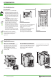
The parameter unit FR-PA02-02 is
available for all frequency inverters. It
provides a clear and easy operation of
the inverter and displays several opera
-
tional and alarm signals. The parameter
unit can be connected remotely via an
extension cable and an adapter (see ac
-
cessories).
앬
The FR-PU04 control panel is option
-
ally available. It provides a long-life
backlight LC display. Operational data
is directly input via the numeric key
-
pad. Eight different selectable lan
-
guages are supported on the display.
The integrated copy function transfers
the entire parameter settings to other
inverters and thus shortens the initiali
-
sation time significantly.
This parameter unit will be connected
remotely via an optional extension cable.
All parameters can be assigned to
user groups thus supplying only the
required parameters for specific
applications.
Simplified Maintenance
Easy access to cooling fans
The easily accessible cooling fans can be
replaced quickly and easily if required.
The lifetime of the cooling fans can be
extended significantly through a
selective ON/OFF control specified by
parameter 244.
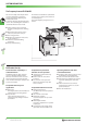
Easy installation and maintenance
Since the control and power terminal block
is easy of access, the installation and main
-
tenance of the inverter is also very easy.
All connection points are designed as
screw terminals.
The housing includes a cable routing
facility which can be removed for in-
stalling.
The inverter can be controlled alternatively
via the parameter unit or through an
RS485 interface via a personal
computer.
For setting, parameterizing, and monito
-
ring via a personal computer the
VFD Setup Software is required
(refer to page 15 for further details).
RUN
STOP
RESET
FR-PA02
-02
Hz
PU
FR-PA02-02
EXT
PU
FWD
REV
STOP
RESET
WRITE
READ
MON
HELP
7
4
1
0
2
3
8
5
6
9
SET
SHIFT
ESC
F
R
-
P
U
-
0
4
PARAMETER UNIT
---
STOP
EXT
50
0
0
Hz
FR-PU04
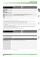
SINK
P1
-
+
PR
RH
A
RM
B
RL
C
MRS
10
RES
2
SD
SD
5
AM
4
PC
PC
SD
SE
SE
STF
RUN
STR
FAN
2
FAN
1
FU
SD
SOURCE
SINK
P1
-
+
PR
RH
A
RM
B
RL
C
MRS
10
RES
2
SD
SD
5
AM
4
PC
PC
SD
SE
SE
STF
RUN
STR
FAN
2
FAN
1
FU
SD
SOURCE
POWER
ALARM
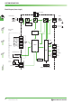
SYSTEM DESCRIPTION
FR-E 520S EC