
Specifications


8
MITSUBISHI ELECTRIC
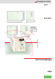
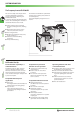
FR-E 500 EC
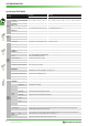
Specifications FR-E 500 EC
Product line
FR-E 520S EC FR-E 540 EC
0.4 k
0.75 k 1.5 k 2.2 k
0.4 k
0.75 k 1.5 k 2.2 k 3.7k 5.5 k 7.5 k
Output
Rated motor
capacity [kW]
150 % Overload capacity
0.75 1.1 2.2 3 0.75 1.1 2.2 3 4 7.5 11
200 % Overload capacity
0.4 0.75 1.5 2.2 0.4 0.75 1.5 2.2 4 5.5 7.5
Rated current
[A]
150 % Overload capacity
3.6 5 9.6 12 1.8 3 4.9 6.7 9.5 14 21
200 % Overload capacity
2.5 4 7 10 1.6 (1.4) 2.6 (2.2) 4 (3.8) 6 (5.4) 9.5 (8.7) 12 17
Rated output capacity kVA 0.95 1.5 2.7 3.8 1.2 2.0 3.0 4.6 7.2 9.1 13.0
Overload
capacity
150 % of rated motor capacity for 0.5 s; 120 % for 1 min. (max. ambient temperature = 50 °C)
200 % of rated motor capacity for 0.5 s; 150 % for 1 min. (max. ambient temperature = 50 °C)
Voltage
3-phase, 0 V up to power supply voltage
Input
Power supply voltage 1-phase, 200–240 V AC, −15 % / +10 % 3-phase, 380–480 V AC, −15 % / +10 %
Voltage range 170–264 V AC at 50 / 60 Hz 323–528 V AC at 50 / 60 Hz
Frequency range 50 / 60 Hz ± 5 % 50 / 60 Hz ± 5 %
Rated input capacity
kVA 1.5 2.3 4.0 5.2 1.5 2.5 4.5 5.5 9 12 17
Control
specifi-
cations
Control method Extended flux vector control with online auto tuning of motor data or V/f control
Modulation control Sine evaluated PWM, Soft PW
Carrier frequency 0.7–14.5 kHz (user adjustable)
Frequency range 0.2–400 Hz
Frequency
resolution
Analog From terminals 2-5: 1/500 of maximum set frequency(input 5 V DC); 1/1000 (input 10 V, 20 mA DC)
Digital 0.01 Hz / 50 Hz
Frequency precision
±0.5 % of max. output frequency (temperature range 25 °C±10 °C) during analog input;
±0.01 % of max. output frequency during digital input
Voltage /
frequency characteristics
Base frequency adjustable from 0 to 400 Hz;
constant torque or variable torque selectable
Possible starting torque ≥ 150 % / 1 Hz, ≥ 200 % / 3Hz (for vector control oder slip compensation)
Torque boost Manual torque boost; selectable between 0–30 %
Acceleration / deceleration time 0.01; 0.1 to 3600 s individual settings
Acceleration / deceleration characteristics Linear or S-form course, user selectable
Braking torque
Regenerative
0.4 k and 0.75 k: 100 % or more; 1.5 k: 50 % or more; 2.2 k to 7.5 k: 20 % or more
DC braking
Braking time and braking moment adjustable,
Operating frequency: 0–120 Hz, operating time: 0–10 s, voltage: 0–30 %
Current stall prevention operation level Operation current level setting possible (0–200 % variable), enable/disable selection
Voltage stall prevention operation level Operation level is fixed, enable/disable selection
High-response current restriction level Operation level is fixed, enable/disable selection
Motor protection Electronic motor protection relay (rated current user adjustable)
Control
signals for
operation
Frequency
setting values
Analog input 0–5 V DC, 0–10 V DC, 0/4–20 mA
Digital input From control panel (parameter unit), RS-485 or network
Input
signals
Starting signal
Individual selection of forward / reverse run
Starting signal self retaining input
Multi-speed selection Up to 15 set speeds (each speed can be set between 0 and 400 Hz; speed can be changed via control panel or during operation)
2nd function Selects 2nd function (acceleration time, deceleration time, torque boost, base frequency, electronic overcurrent protection)
Selection of
current input
Frequency setting via current input signal 0/4 to 20 mA DC
External
thermal input
Stopping the inverter with an externally mounted thermal relay
PU<->external
operation
Switch over between the operating modes "PU" and "External"
V/F<->flux vector
control
External switching between V/F control and general-purpose flux vector control
Output stop Instant cutoff of inverter output (frequency and voltage)
Error reset The error indication (alarm signal) is reset with the reset of the protective function
Operation functions
Maximum and minimum frequency setting, frequency jump operation, external thermal input selection, instantaneous power failure restart
operation, forward run/reverse run prevention, slip compensation, operation mode selection, off-line auto tuning function, PID control,
computer link operation (RS485), open network operation
Output
signals
Operation
status
2 output types (open collector output) can be selected: inverter running, frequency reached, frequency detection, overload warning, zero return
detection, output current detection, maximum PID, minimum PID, PID forward run, PID reverse run, operation ready, minor failure and error.
1 relay contact can be selected for the output (230 V AC; 0.3 A / 30 V DC; 0.3 A)
Analog signal
One of the following output types can be selected:
output frequency, motor current, output voltage, analog output (0–10 V DC).
SYSTEM DESCRIPTION