E700_NA_Guideline_ib0600333ENG.book 1 ページ 2007年11月28日 水曜日 午前10時20分 INVERTER FR-E700 INSTALLATION GUIDELINE FR-E720-008 to 600-NA FR-E740-016 to 300-NA Thank you for choosing this Mitsubishi Inverter. Please read through this Installation Guideline and a CD-ROM enclosed to operate this inverter correctly. Do not use this product until you have a full knowledge of the equipment, safety information and instructions. Please forward this Installation Guideline and the CD-ROM to the end user.
E700_NA_Guideline_ib0600333ENG.book 1 ページ 2007年11月28日 水曜日 午前10時20分 This Installation Guideline provides handling information and precautions for use of the equipment. Please forward this Installation Guideline to the end user. Do not attempt to install, operate, maintain or inspect the inverter until you have read through the Installation Guideline and appended documents carefully and can use the equipment correctly.
E700_NA_Guideline_ib0600333ENG.book 2 ページ 2007年11月28日 水曜日 (2) Wiring 午前10時20分 (5) Emergency stop CAUTION z Do not install a power factor correction capacitor or surge suppressor/capacitor type filter on the inverter output side. z The connection orientation of the output cables U, V, W to the motor will affect the direction of rotation of the motor. (3) Trial run CAUTION z Before starting operation, confirm and adjust the parameters.
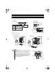
E700_NA_Guideline_ib0600333ENG.book 1 ページ 2007年11月28日 水曜日 午前10時20分 1 PRODUCT CHECKING AND PARTS IDENTIFICATION Unpack the inverter and check the capacity plate on the front cover and the rating plate on the inverter side face to ensure that the product agrees with your order and the inverter is intact.
E700_NA_Guideline_ib0600333ENG.book 2 ページ 2007年11月28日 水曜日 午前10時20分 PRODUCT CHECKING AND PARTS IDENTIFICATION z General Precaution The bus capacitor discharge time is 10 minutes. Before starting wiring or inspection, switch power off, wait for more than 10 minutes, and check for residual voltage between terminal P/+ and N/- with a meter etc., to avoid a hazard of electrical shock. z Environment Before installation, check that the environment meets following specifications.
E700_NA_Guideline_ib0600333ENG.book 3 ページ 2007年11月28日 水曜日 午前10時20分 2 OUTLINE DIMENSION DRAWINGS H H1 When used with the plug-in option W1 D1* D W * When the FR-A7NC E kit is mounted, a terminal block protrudes making the depth approx. 2mm (0.08 inches) greater. (Unit:mm(inches)) • 200V class Inverter Type W W1 H H1 FR-E720-008 FR-E720-015 FR-E720-030 68(2.68) 56(2.20) 128(5.04) FR-E720-050 FR-E720-080 FR-E720-110 FR-E720-175 FR-E720-240 FR-E720-330 FR-E720-470 FR-E720-600 118(4.
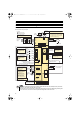
E700_NA_Guideline_ib0600333ENG.book 4 ページ 2007年11月28日 水曜日 午前10時20分 Terminal connection diagram 3 WIRING 3.1 Terminal connection diagram zThree-phase 200V power input zThree-phase 400V power input Brake unit (Option) Sink logic Main circuit terminal Control circuit terminal *1 When connecting a DC reactor, remove the jumper across P1-P/+ MCCB *7 Brake resistor (FR-ABR, MRS, MYS type) Install a thermal relay to prevent an overheat and burnout of the brake resistor.
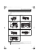
E700_NA_Guideline_ib0600333ENG.book 5 ページ 2007年11月28日 水曜日 午前10時20分 Main circuit terminal specifications 3.2 3.2.1 Main circuit terminal specifications Terminal arrangement of the main circuit terminal, power supply and the motor wiring 200V class FR-E720-008 to 050 FR-E720-080 to 175 Jumper Jumper Screw size (M3.5) N/- P/+ N/- P/+ Screw size (M4) R/L1 S/L2 T/L3 PR PR R/L1 S/L2 T/L3 Screw size (M3.
E700_NA_Guideline_ib0600333ENG.book 6 ページ 2007年11月28日 水曜日 午前10時20分 Main circuit terminal specifications 3.2.2 (1) Cables and wiring length Cable sizes etc., of the main control circuit terminals and earth (ground) terminals Select the recommended cable size to ensure that a voltage drop will be 2% max. If the wiring distance is long between the inverter and motor, a main circuit cable voltage drop will cause the motor torque to decrease especially at the output of a low frequency.
E700_NA_Guideline_ib0600333ENG.book 7 ページ 2007年11月28日 水曜日 午前10時20分 Main circuit terminal specifications (2) Total wiring length The overall wiring length for connection of a single motor or multiple motors should be within the value in the table below. 200V class Pr. 72 PWM frequency selection Setting (carrier frequency) 008 015 1 (1kHz) or less 200m (656.19 feet) 200m (656.19 feet) 300m 500m 500m 500m 500m (984.25 (1640.42 (1640.42 (1640.42 (1640.42 feet) feet) feet) feet) feet) 30m (98.
E700_NA_Guideline_ib0600333ENG.book 8 ページ 2007年11月28日 水曜日 午前10時20分 Main circuit terminal specifications NOTE y Especially for long-distance wiring, the inverter may be affected by a charging current caused by the stray capacitances of the wiring, leading to a malfunction of the overcurrent protective function, fast response current limit function, or stall prevention function or a malfunction or fault of the equipment connected on the inverter output side.
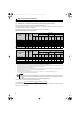
E700_NA_Guideline_ib0600333ENG.book 9 ページ 2007年11月28日 水曜日 午前10時20分 Control circuit specifications 3.3 (1) Control circuit specifications Standard control circuit terminal layout Terminal screw size M3: (Terminal A, B, C) M2: (Other than the above) 10 2 5 4 RUN FU SE AM RL RM RH MRS RES SD PC STF STR SD SD A (2) B C Wiring method 1) Strip off the sheath of the cable of the control circuit to wire. Strip off the sheath about the size below.
E700_NA_Guideline_ib0600333ENG.book 10 ページ 2007年11月28日 水曜日 午前10時20分 PRECAUTIONS FOR USE OF THE INVERTER 4 PRECAUTIONS FOR USE OF THE INVERTER The FR-E700 series is a highly reliable product, but incorrect peripheral circuit making or operation/handling method may shorten the product life or damage the product. Before starting operation, always recheck the following items. (1) Use crimping terminals with insulation sleeve to wire the power supply and motor.
E700_NA_Guideline_ib0600333ENG.book 11 ページ 2007年11月28日 水曜日 午前10時20分 PRECAUTIONS FOR USE OF THE INVERTER (12) Do not apply a voltage higher than the permissible voltage to the inverter I/O signal circuits. Application of a voltage higher than the permissible voltage to the inverter I/O signal circuits or opposite polarity may damage the I/O devices. Especially check the wiring to prevent the speed setting potentiometer from being connected incorrectly to short terminals 10-5.
E700_NA_Guideline_ib0600333ENG.book 12 ページ 2007年11月28日 水曜日 午前10時20分 FAILSAFE OF THE SYSTEM WHICH USES THE INVERTER 5 FAILSAFE OF THE SYSTEM WHICH USES THE INVERTER When a fault occurs, the inverter trips to output a fault signal. However, a fault output signal may not be output at an inverter fault occurrence when the detection circuit or output circuit fails, etc.
E700_NA_Guideline_ib0600333ENG.book 13 ページ 2007年11月28日 水曜日 午前10時20分 PARAMETER LIST 6 PARAMETER LIST For simple variable-speed operation of the inverter, the initial setting of the parameters may be used as they are. Set the necessary parameters to meet the load and operational specifications. Parameter setting, change and check can be made from the operation panel. For details of parameters, refer to the instruction manual. REMARKS y indicates simple mode parameters.
E700_NA_Guideline_ib0600333ENG.book 14 ページ 2007年11月28日 水曜日 午前10時20分 PARAMETER LIST Setting Range Name Parameter Initial Value 0, 5, 7 to 12, 52 DU/PU main display data 14, 20, 23 to selection 25, 52 to 57, 89 0 61, 62, 100 55 Frequency monitoring reference 0 to 400Hz 60Hz Rated 56 Current monitoring reference 0 to 500A inverter current 57 Restart coasting time 0, 0.
E700_NA_Guideline_ib0600333ENG.
E700_NA_Guideline_ib0600333ENG.
E700_NA_Guideline_ib0600333ENG.
E700_NA_Guideline_ib0600333ENG.book 18 ページ 2007年11月28日 水曜日 午前10時20分 Reset method of protective function 7 TROUBLESHOOTING When a fault occurs in the inverter, the inverter trips and the PU display automatically changes to any of the following fault or alarm indications. If the fault does not correspond to any of the following faults or if you have any other problem, please contact your sales representative. z Retention of fault output signal...
E700_NA_Guideline_ib0600333ENG.book 19 ページ 2007年11月28日 水曜日 午前10時20分 List of fault or alarm indications List of fault or alarm indications Operation Panel Operation Panel Name Indication Fault Alarm Warnings Error message E--HOLD to Er1 to 4 Name Indication Faults history E.ILF ∗ Input phase loss Operation panel lock E.OLT Stall prevention E. BE Brake transistor alarm detection E.GF Output side earth(ground) fault overcurrent protectionat start E.
E700_NA_Guideline_ib0600333ENG.book 20 ページ 2007年11月28日 水曜日 午前10時20分 Appendix 1 Instructions for Compliance with the European Directives (1) EMC Directive 1) Our view of transistorized inverters for the EMC Directive A transistorized inverter is a component designed for installation in an enclosure and for use with the other equipment to control the equipment/device. Therefore, we understand that the EMC Directive does not apply directly to transistorized inverters.
E700_NA_Guideline_ib0600333ENG.book 21 ページ 2007年11月28日 水曜日 午前10時20分 yTo use the inverter outside of an enclosure in the environment of pollution degree 2, fix a fan cover with fan cover fixing screws enclosed.
E700_NA_Guideline_ib0600333ENG.book 22 ページ 2007年11月28日 水曜日 午前10時20分 Appendix 2 Instructions for UL and cUL (Standard to comply with: UL 508C, CSA C22.2 No. 14) 1. General Precaution The bus capacitor discharge time is 10 minutes. Before starting wiring or inspection, switch power off, wait for more than 10 minutes, and check for residual voltage between terminal P/+ and N/- with a meter etc., to avoid a hazard of electrical shock. 2.
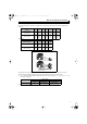
E700_NA_Guideline_ib0600333ENG.book 23 ページ 2007年11月28日 水曜日 午前10時20分 5. Motor overload protection When using the electronic thermal relay function as motor overload protection, set the rated motor current to Pr. 9 "Electronic thermal O/L relay". Pr. 9 = 100% setting of inverter rating*2 Pr. 9 = 50% setting of inverter rating*1, 2 Operation time (min) (min) unit display in this range Electronic thermal relay function operation characteristic 70 30Hz or more *3 20Hz 60 10Hz 6Hz 50 0.
E700_NA_Guideline_ib0600333ENG.
E700_NA_Guideline_ib0600333ENG.book 25 ページ 2007年11月28日 水曜日 午前10時20分 REVISIONS *The manual number is given on the bottom left of the back cover. Print Date *Manual Revision Number Sep., 2007 IB-0600333ENG-A Nov., 2007 IB-0600333ENG-B First edition Additions • FR-E740-230, 300 For Maximum Safety • Mitsubishi inverters are not designed or manufactured to be used in equipment or systems in situations that can affect or endanger human life.