
Instruction manual


5
Main circuit terminal specifications
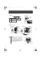
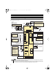
3.2 Main circuit terminal specifications
3.2.1 Terminal arrangement of the main circuit terminal, power supply and the motor
wiring
200V class
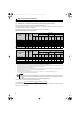
400V class
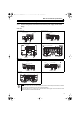
FR-E720-008 to 050 FR-E720-080 to 175
FR-E720-240, 330 FR-E720-470, 600
FR-E740-016 to 095 FR-E740-120, 170
FR-E740-230, 300
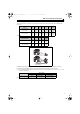
NOTE
y Make sure the power cables are connected to the R/L1, S/L2, T/L3. Never connect the power cable to the U, V, W of the
inverter. Doing so will damage the inverter. (Phase need not be matched.)
y Connect the motor to U, V, W. Turning on the forward rotation switch (signal) at this time rotates the motor
counterclockwise when viewed from the load shaft.
Screw size
(M3.5)
MotorPower supply
N/-
P/+ PR
IM
R/L1 S/L2 T/L3
Jumpe
r
Screw size (M3.5)
Screw size
(M4)
Motor
Power supply
N/-
P/+
PR
IM
R/L1 S/L2 T/L3
Jumper
Screw size (M4)
Motor
Power supply
IM
N/-
P/+
PR
R/L1 S/L2 T/L3
Jumper
Screw size (M5)
Screw size
(M5)
N/-
P/+
PR
R/L1 S/L2 T/L3
Jumper
Screw size(470:M5/600:M6)
Screw size
(M5)
MotorPower supply
IM
N/-
P/+
PR
R/L1 S/L2 T/L3
Screw size
(M4)
MotorPower supply
IM
Jumper
Screw size (M4)
N/-
P/+
PR
R/L1 S/L2 T/L3
Screw size (M4)
Screw size
(M4)
MotorPower supply
Jumper
IM
Motor
Power supply
IM
N/-
P/+
PR
R/L1 S/L2 T/L3
Jumper
Screw size
(230: M4/300: M5)
Screw size (230: M4/300: M5)
E700_NA_Guideline_ib0600333ENG.book 5 ページ 2007年11月28日 水曜日 午前10時20分