VECTOR INVERTER FR-V500 FR-V500 INSTRUCTION MANUAL (BASIC) FR-V520-1.5K to 55K FR-V540-1.5K to 55K VECTOR INVERTER Thank you for choosing this Mitsubishi Vector Inverter. If this is the first time for you to use the FR-V500 series, please read through this Instruction Manual (basic) carefully to use the inverter safely.
This Instruction Manual (basic) provides handling information and precautions for use of the equipment. Please forward this Instruction Manual (basic) to the end user. This section is specifically about safety matters Do not attempt to install, operate, maintain or inspect the inverter until you have read through the Instruction Manual and appended documents carefully and can use the equipment correctly.
2) Wiring CAUTION z Do not fit capacitive equipment such as power factor correction capacitor, surge suppressor or radio noise filter (option FR-BIF) to the inverter output side. z The connection orientation of the output cables (terminals U, V, W) to the motor will affect the direction of rotation of the motor. 3) Trial run CAUTION z Check all parameters, and ensure that the machine will not be damaged by a sudden start-up.
1 OUTLINE Harmonic Suppression Guideline All models of general-purpose inverters used by specific consumers are covered by "Harmonic suppression guideline for consumers who receive high voltage or special high voltage". (For further details, refer to Instruction Manual (detailed).
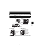
Basic configuration and connection of peripheral devices 1.1 Basic configuration and connection of peripheral devices 1.1.1 Basic configuration Power supply Use within the permissible power supply specifications of the inverter. (Refer to page 103.) (MCCB) or (ELB) Moulded case circuit breaker (MCCB) or earth leakage circuit breaker (ELB) The breaker must be selected carefully since an in-rush current flows in the inverter at power-on. (Refer to page 3.
Basic configuration and connection of peripheral devices 1.1.2 Selection of peripheral devices Check the motor applicable to the inverter you purchased. Appropriate peripheral devices need to be selected according to the motor capacity. Refer to the list below and prepare appropriate peripheral devices. 200V class *1 1.5 2.2 3.7 5.5 7.5 11 15 18.5 22 30 37 45 55 Applicable Inverter Type Standard FR-V520-1.5K FR-V520-2.2K FR-V520-3.7K FR-V520-5.5K FR-V520-7.5K FR-V520-11K FR-V520-15K FR-V520-18.
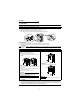
Structure 1.2 Structure 1.2.1 Removal and reinstallation of the front cover FR-V520-1.5K to 7.5K, FR-V540-1.5K to 5.5K z Removal 1) 2) Hold both sides of the front cover top and push the front cover down. Hold down the front cover and pull it toward you to remove. (The front cover may be removed with the PU (FR-DU04-1/FR-PU04V) on.) Hook Inverter Front cover z Reinstallation 1) Insert the hooks at the bottom of the front cover into the sockets of the inverter.
Structure REMARKS • Removal of the wiring port cover for option (DATA PORT) Push the DATA PORT from the back of the front cover to remove before fitting the communication option. 1.2.2 Wiring port cover for option (DATA PORT) . Removal and reinstallation of the control panel To ensure safety, remove and reinstall the control panel after powering off. z Removal Hold down the top button of the control panel and pull the control panel toward you to remove.
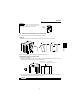
Installation of the inverter 2 INSTALLATION AND WIRING 2.1 Installation of the inverter z Install the inverter under the following conditions. Vertical mounting 10cm or more Measurement position Inverter 5cm Measurement position Vertical 5cm 5cm or more * 5cm 5cm or more * 5cm Inverter or more 10cm or more Temperature: -10°C to 50°C Humidity: 90%RH maximum. Leave enough clearances and take cooling measures.
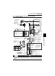
Connection diagram, encoder cable, PU connector 2.2 Connection diagram, encoder cable, PU connector 2.2.1 Connection diagram (Dedicated Motor: SF-V5RU) Avoid frequent ON-OFF. Repeated inrush currents at power-on will shorten the converter life. (Switching life is 100,000) Three-phase AC power supply MCCB R MC OCR B T C Vector inverter (FR-V500) MCCB MC U R V S W T R1 OH SD S1 PA Take care not to short terminals PC-SD.
Connection diagram, encoder cable, PU connector 2.2.2 Main circuit terminal specifications (1) Specification of main circuit terminal Terminal Symbol Terminal Name DC reactor connection Built-in brake circuit connection Earth (Ground) For earthing (grounding) the inverter chassis. Must be earthed (grounded).
Connection diagram, encoder cable, PU connector (2) Terminal arrangement of the main circuit terminal In the main circuit of the inverter, the terminals are arranged as shown below: 200V class FR-V520-1.5K, 2.2K Jumpers FR-V520-18.5K Jumpers Screw size (M4) Jumpers Charge lamp R S T U V W N P P1 R1 S1 R1 S1 PR R PX Charge lamp Screw size (M4) S Screw size (M8) IM Power supply Motor R Screw size (M4) S T U V W P1 N P Jumper IM Screw size (M6) FR-V520-3.7K, 5.5K, 7.
Connection diagram, encoder cable, PU connector 400V class FR-V540-1.5K, 2.2K FR-V540-18.5K Jumpers Jumpers Jumpers Screw size (M4) Charge lamp R1 S1 R S U T V W P1 N R R1 S1 S Screw size (M6) PX Charge lamp IM Power supply Screw size (M4) PR P R S T U V W N P1 Motor IM Screw size (M4) P Jumper Screw size (M6) FR-V540-3.7K, 5.
Connection diagram, encoder cable, PU connector (3) Cables and wiring length Select the recommended cable size to ensure that a voltage drop will be 2% max. If the wiring distance between the inverter and motor is long, the motor torque will decrease due to the voltage drop of the main circuit cable especially at high-frequency output. The encoder signal will also be affected by the voltage drop. The following selection example assumes the wiring length of 20m.
Connection diagram, encoder cable, PU connector 2.2.3 Encoder connection cable (FR-V5CBL) When using a dedicated motor (SF-V5RU series), use an encoder cable (FR-V5CBL) for connection. Inverter side Earth (Ground) wire Encoder side connector MS3057-12A F-DPEVSB 12P×0.2mm2 11 60 FR-V500 PA PAR PB PBR PZ PZR MS3106B20-29S L (Unit: mm ) Encoder Type Length L (m) A B C D F G FR-V5CBL5 FR-V5CBL15 FR-V5CBL30 5 15 30 Remarks Standard product Contact us separately for other lengths.
Connection diagram, encoder cable, PU connector z Encoder output jumper connector circuit Complimentary (CMP) Terminating resistance The jumper connector is fitted to complimentary when shipped from the factory. Switch its position according to output circuit. Differential line driver (LDV) Terminating resistance (2) Setting the number of encoder pulses and encoder rotation direction Set the following parameters according to the encoder specification.
Connection diagram, encoder cable, PU connector 2.2.
Connection diagram, encoder cable, PU connector Open collector RS-485 Communication Analog Output signals Contact Type Terminal Symbol Terminal Name Description 1 changeover contact output indicates that the inverter protective function activated and the output stopped. 230VAC 0.3A, 30VDC 0.3A. Alarm: discontinuity across B-C (continuity across A-C), Normal: continuity across B-C (discontinuity across A-C).
Connection diagram, encoder cable, PU connector (4) Connecting the control circuit to a power supply separately from the main circuit If the magnetic contactor (MC) in the inverter power supply is opened when the protective circuit is operated, the inverter control circuit power is lost and the alarm output signal cannot be kept on. To keep the alarm signal on terminals R1 and S1 are available. In this case, connect the power supply terminals R1 and S1 of the control circuit to the primary side of the MC.
Connection diagram, encoder cable, PU connector (5) Changing the control logic The input signals are factory set to sink logic (SINK). To change the control logic, the jumper connector on the back of the control circuit terminal block must be moved to the other position. (The output signals may be used in either the sink or source logic independently of the jumper connector position.) 1) Loosen the two mounting screws in both ends of the control circuit terminal block. (The screws cannot be removed.
Connection diagram, encoder cable, PU connector 4) Sink logic type and source logic type • In sink logic, a signal switches on when a current flows from the corresponding signal input terminal. Terminal SD is common to the contact input signals. Terminal SE is common to the open collector output signals. • In source logic, a signal switches on when a current flows into the corresponding signal input terminal. Terminal PC is common to the contact input signals.
Connection diagram, encoder cable, PU connector 2.2.6 Connection to the PU connector (1) When connecting the control panel or parameter unit using a connection cable • Parameter unit connection cable (FR-CB2 ) (option) or the following connector and cable available on the market • Connector : RJ45 connector Example: 5-554720-3 of Tyco Electronics Corporation • Cable : Cable conforming to EIA568 (e.g. 10BASE-T cable) Example: SGLPEV-T 0.
Setting the motor 2.3 Setting the motor This inverter is factory-set to run the dedicated motor (SF-V5RU (1500r/min series) with encoder) 0 10 SF-JR SF-HRCA Inverter internal constants Inverter internal constants (It is not necessary to reset the inverter if you use the dedicated motor (SF-V5RU (1500r/min series) with encoder) (only when inverter capacity = motor capacity).) POINT The parameter below is extended mode parameter. Set "1" in Pr. 160 "extended function selection". 2.3.
Setting the motor REMARKS 1 2 3 4 5 6 7 8 9 1. 2. 3. 4. 5. Item Motor setting Offline tuning Parameter, Jumper Connector, Terminal Pr. 71 setting Dedicated Motor Mitsubishi Mitsubishi SF-JR (with encoder) SF-V5RU SF-VRSF-HR (4P)1500r/min 5.5kW to (2, 4, 6P)(with 2.2kW to 1.
Precautions for use of the vector inverter 2.4 Precautions for use of the vector inverter The FR-V500 series is a highly reliable product, but incorrect peripheral circuit making or operation/handling method may shorten the product life or damage the product. Before starting operation, always recheck the following items. (1) Use insulation-sleeved crimping terminals for the power supply and motor cables. (2) The inverter will be damaged if power is applied to the inverter output terminals (U, V, W).
Checks prior to test run 3 RUN AND OPERATION 3.1 Checks prior to test run Installation check Check that the inverter is installed correctly in a correct place. (Refer to page 6.) Wiring check Check that wiring is correct. (Refer to page 7.) 3.2 Basic operation (Speed setting, run, speed meter adjustment) 3.2.
Basic operation (Speed setting, run, speed meter adjustment) z PU jog operation Hold down FWD or REV to perform operation, and release it to stop. 1)Set Pr. 15 "jog speed setting" and Pr. 16 "jog acceleration/deceleration time". 2)Set PU jog operation. (Press operation.) MODE to select the operation mode and press to switch to PU jog 3)Hold down the FWD or REV key to perform operation. (If the motor remains stopped, check Pr. 13 "starting speed".
Basic operation (Speed setting, run, speed meter adjustment) z External jog operation Keep the start switch (STF or STR) on to perform operation, and turn it off to stop. 1)Set Pr. 15 "jog speed setting" and Pr. 16 "jog acceleration/deceleration time". 2)Select the external operation mode. 3)Switch on the jog signal. Keep the start switch (STF or STR) on to perform operation. Assign the terminal used for the jog signal in any of Pr. 180 to Pr. 183 and Pr. 187 (input terminal function selection).
Basic operation (Speed setting, run, speed meter adjustment) 3.2.2 Adjustment (calibration) of speed meter (meter) Changing example At the preset speed of 1500r/min, make adjustment so that the meter (analog meter) deflects to full-scale. Calibrate the DA1 terminal (±10V).(in PU operation mode) POINT • Pr. 900 "DA1 terminal calibration" can be read by setting "1" (extended function parameter enable) in Pr. 160 "extended function selection". • Set Pr. 900 "DA1 terminal calibration".
Names and functions of the control panel 3.3 Names and functions of the control panel With the control panel (FR-DU04-1), you can perform operation, set the speed, monitor the run command display, set parameters, display an error, and copy parameters.
Names and functions of the control panel 3.3.
Names and functions of the control panel 3.3.4 Parameter setting method (Example: Method to enable extended function parameters) • A parameter value may either be set by updating its parameter number or setting the value digit-by-digit using . • To write the setting, change it and press SET for 1.5s. Example: To change the Pr. 160 "extended function selection" setting from "0" (extended function parameter invalid) to "1" (extended function parameter valid) (Refer to page 56 for details of Pr. 160.
Names and functions of the control panel 3.3.6 Help mode Alarm history FR-DU04-1 Alarm history clear CONTROL PANEL Parameter clear All clear Software version read Hz/r A V MON EXT PU REV FWD MODE To 3.3.2 Monitoring (1) Alarm history Four past alarms can be displayed with ("." is appended to the latest alarm.) When no alarm exists, . is displayed.
Names and functions of the control panel (3) Parameter clear Initializes the parameter values to the factory settings. The calibration values are not initialized. (Parameter values are not cleared by setting "1" in Pr. 77 "parameter write disable selection".
Names and functions of the control panel 3.3.7 Copy mode By using the control panel (FR-DU04-1), the parameter values can be copied to another inverter (only the FR-V500 series). 1) Operating procedure After reading the parameter values from the copy source inverter, connect the control panel to the copy destination inverter, and write the parameter values. After writing the parameter values to the copy destination inverter, always reset the inverter, e.g. switch power off once, before starting operation.
Speed control operation 4 CONTROL This inverter can control a motor under speed, torque or position control. (As required, set "1" (extended function parameters valid) in Pr. 160 "extended function selection".) Refer to page 29 for the setting method of Pr. 160 "extended function selection" and to page 56 for details. (Since the factory setting of Pr. 77 is "0", perform parameter write in the PU mode or during a stop.) 4.1 Speed control operation 4.1.
Speed control operation 4.1.4 Run command setting (1) Forward and reverse rotation commands (terminals STF, STR) 1) Command from the control panel (FR-DU04-1): Turn on FWD or REV (Refer to page 23.). 2) External command: Turn the forward/reverse rotation signal (terminal STF, STR) on. (Refer to page 24.) (Turning both terminals STF and STR on or off will give a stop command.) REMARKS Use Pr. 79 "operation mode selection" to change the operation mode between control panel (PU) and external command (EXT).
Speed control operation Parameter Factory Setting Name 22 Torque limit level 811 Set resolution switchover 812 Torque limit level (regeneration) 9999 813 Torque limit level (3rd quadrant) 9999 814 Torque limit level (4th quadrant) 9999 815 Torque limit level 2 9999 816 817 150 0 Acceleration torque limit level Deceleration torque limit level 9999 9999 Description Set the torque limit level in % for speed control or position control so that the output torque does not exceed the predet
Speed control operation (2) Second torque limit level z When the TL signal is on, the Pr. 815 value is a torque limit value regardless of the setting in Pr. 810. Torque limit Forward driving Reverse regeneration Pr. 815 - quad 4 Pr. 815 1500 r/min quad 3 quad 1 1500 r/min quad 2 Reverse driving Reverse rotation Pr. 815 + Speed Pr. 815 Forward regeneration Forward rotation Related parameters TL signal terminal assignment ⇒ Set "26" in any of Pr. 180 to Pr. 183 and Pr.
Speed control operation (5) Change the torque characteristics in the constant power range (Pr. 803) Torque command Constant power range Constant torque range Pr. 803 = 1: constant torque limit Pr. 803 = 0: constant power limit (torque reduction) Base speed 4.1.6 • You can select whether the torque limit in the constant power range be constant torque limit (setting is "1") or constant power limit (initial setting is "0"), using Pr.
Torque control operation 4.2 Torque control operation 4.2.1 Torque control Torque control is exercised to develop torque as set in the torque command. The motor speed becomes constant when the motor output torque and load torque are balanced. For torque control, therefore, the speed is determined by the load. For torque control, the motor gains speed as the motor output torque becomes greater than the motor load. Here, set the speed limit value so that the motor speed does not increase too high.
Torque control operation (1) I/O signals The following table indicates the operations of the signals. Signal Terminal Name Remarks External operation Start signal Torque command Speed limit STF, STR signal Forward or reverse rotation from PU operation PU04V or DU04-1 As set in the torque command source selection parameter. As set in the speed limit selection parameter. Start and stop are the same as under speed control. A stop is made when the STF and STR signals are both on. Input torque command.
Torque control operation 4.2.3 Setting procedure Perform secure wiring. (Refer to page 7.) It is not necessary to set the encoder and motor when using the dedicated motor (SF-V5RU). Set the encoder. (Refer to page 12.) Set the motor to be used. (Refer to page 20.) Refer to page 20 if the motor is one rank lower. Set any of "1 (torque control), 2 (speed-torque switchover), 5 (position-torque switchover)" in Pr. 800 "control method selection" to make torque control valid. (Refer to page 57.
Torque control operation z16bit two’s complement Torque command Hexadecimal Decimal -327.68% -32768 8000H 32768 -100% -10000 D8F0H 55536 -50% -5000 EC78H 60536 -25% -2500 F63CH 63036 0% 0000 0 0 25% 2500 09C4H 2500 50% 5000 1388H 5000 100% 10000 2710H 10000 327.67% 32767 7FFFH 32767 CAUTION • The internal resolution of the torque command is 0.024% (100/212) and the fraction less than the resolution is rounded off. • The range of torque setting is from -327.68% to 327.67%.
Torque control operation 4.2.6 Speed limit Set the speed limit value to prevent the motor from over speeding due to a smaller load torque than the torque command value. Parameter Name Factory Setting Setting Range 807 808 809 Speed limit selection Forward rotation speed control Reverse rotation speed control 0 1500r/min 9999 0, 1, 2 0 to 3600r/min 0 to 3600r/min, 9999 Select the speed limit input method using Pr. 807. Pr.
Torque control operation (1) When Pr. 807 = 0 The speed command value during speed control acts as a speed limit level. At this time, according to the acceleration/deceleration time set in Pr. 7 "acceleration time" and Pr. 8 "deceleration time", the limit level is increased from 0r/min upon start, and when the start signal turns off, the speed limit level is decreased from the then speed limit level to the DC injection brake operation speed in Pr. 10 to a stop.
Position control operation 4.3 Position control operation On this inverter, you can use parameter and pulse inputs to exercise position control. Refer to the Instruction Manual (detailed) for details. 4.3.1 Position command from parameter setting Position control is exercised using the position feed amounts set in Pr. 465 to Pr. 494. 4.3.
Control mode switchover timing 4.4 Control mode switchover timing Depending on a parameter setting change or whether the MC terminal turns on/off, the control mode switches at the following timing. Switchover Pattern Switchover Operation The mode can be changed any time independently of whether the motor is at a stop or running or Torque the DC brake (servo lock) is operating. Position The mode can be changed when the speed is equal to or lower than the low speed detection level.
Control mode switchover timing Classification Description Analog output Pr.800 setting Terminal name DA1 DA2 0 Speed control Multi-function monitor 1 Multi-function monitor 2 1 2 3 4 5 Torque control MC signal ON OFF Speed Torque control control Position control ← ← ← ← ← ← ← ← ← ← MC signal MC signal ON OFF ON OFF Speed Position Position Torque control control control control *: Assumes that the Pr. 868 value is the factory setting.
Easy gain tuning 4.5 Easy gain tuning The ratio of the load inertia to the motor inertia (load inertia moment ratio) is estimated in real time from the torque command and speed during motor operation to automatically set the optimum gains for speed control/ position control from that ratio and response level setting. 4.5.1 Parameter Parameter Name Factory Setting Setting Range 818 Easy gain tuning response level setting 2 1 to 15 819 Easy gain tuning selection 0 0, 1, 2 4.5.
Easy gain tuning 4.5.3 Precautions for easy gain tuning (1) Checking the Pr. 800 "control method selection" value Easy gain tuning is valid only for the speed control/position control mode under vector control with encoder. It is invalid for torque control and V/F control. Pr.
Easy gain tuning 4.5.5 Easy gain tuning-related parameter operation Refer to the following table for the parameter/gain read/write operation using Pr. 819 "easy gain tuning selection". Pr. 819 = 0 Without tuning Read Setting is displayed. Write Setting can be changed. Pr. 880 "load inertia" Timing of writing load inertia ratio and control — Not written gains into E2PROM Control gains (Pr. 820, Pr. 821, Pr. 828, Pr. 422) Read Write Settings are displayed. Settings can be changed. Pr.
Online auto tuning 4.6 Online auto tuning Excellent torque accuracy is provided by temperature compensation even if the secondary resistance value of the motor varies with the rise in the motor temperature. 4.6.1 Parameters • For the motor with encoder, set "2" in Pr. 95 "online auto tuning selection". Parameter 95 4.6.
Biases and gains of speed setting terminals (Pr. 902 to Pr. 905, Pr. 917 to Pr. 920) 4.7 Biases and gains of speed setting terminals (Pr. 902 to Pr. 905, Pr. 917 to Pr. 920) Adjust the biases and gains of the speed setting terminal 2, torque command terminal 3 and multi-function terminal 1. The "bias" and "gain" functions are designed to adjust the relationship between the 0 to 10V input signal, which is externally input for the setting of output speed, torque or magnetic flux.
Biases and gains of speed setting terminals (Pr. 902 to Pr. 905, Pr. 917 to Pr. 920) There are the following three methods to adjust the speed setting voltage bias and gain. 1) Method to adjust any point by application of a voltage to across terminals 2(1)(3) - 5 2) Method to adjust any point without application of a voltage to across terminals 2(1)(3) - 5 3) Method that does not adjust the bias voltage (Example) Pr. 903 "speed setting terminal 2 gain" (Pr. 902 to Pr.
Biases and gains of speed setting terminals (Pr. 902 to Pr. 905, Pr. 917 to Pr. 920) (4) Set the gain speed in Pr. 903 and display the analog voltage value across terminals 2-5 in %. (To change to 1000r/min) Gain speed changing Currently set gain speed FR-DU04 -1 FR-DU04 -1 CONTROL PANEL Hz/r A V MON EXT PU REV FWD Hz/r A V MON EXT PU REV FWD Analog voltage value (%) across terminals 2-5 Press for 1.
Function list (Simple mode parameters) 5 PARAMETERS 5.
Function list (Simple mode parameters) 5.1.2 Explanation of simple mode parameters Refer to the separately available Instruction Manual (detailed) for details. Pr. 1 "maximum speed", Pr. 2 "minimum speed" z You can clamp the upper and lower limits of the output speed. Pr. 4 "multi-speed setting (high speed)" Pr. 5 "multi-speed setting (middle speed)" Pr. 6 "multi-speed setting (low speed)" z You can select any speed (RH, RM, RL) by simply switching the external contact signal. Speed Maximum speed Pr.
Function list (Simple mode parameters) Pr. 79 "operation mode selection" z The inverter operation mode can be changed as desired between operation using external signals (external operation), operation from the PU (FR-DU04-1/FR-PU04V), combined operation of PU operation and external operation (external/PU combined operation), and computer link operation (when the FR-A5NR option is used). Pr. 79 Setting Function 0 At power-on, the inverter is placed in the external operation mode.
Function list (Simple mode parameters) Pr. 800 "control method selection" z Select the inverter control system such as speed control, torque control or position control.
Function list (Extended function parameters) 5.2 Function list (Extended function parameters) Refer to page 54 for the function list of simple mode parameters. The extended function parameters are made valid by setting "1" in Pr. 160 "extended function selection". Parameter Refer to page 29 for the setting method and to the Instruction Manual (detailed) for details.) Function ( Factory Setting Outline 0 Torque boost (manual) Made valid for V/F control. 0 to 30% 4%/3%/2% (3.7K or less/5.5K, 7.
24 Multi-speed setting (speed 4) 25 Multi-speed setting (speed 5) { { ×* 9999 { { ×* 9999 { { ×* 9999 { { ×* 0 { { × 0 { { × 0 { { { 31 Speed jump 1A 9999 { { 32 Speed jump 1B 9999 { { 9999 { { 9999 { { 35 Speed jump 3A 9999 { { 36 Speed jump 3B 9999 { { × × × × × × 0 { { { 10% { × × 300r/min { { { 9999 { { { 5s { { ×* 9999 { { ×* 750r/min { { { 26 Multi-speed setting (speed 6) 27 Multi-speed setting (speed 7) 28 Multi-sp
Parameter Function Function list (Extended function parameters) Display functions 52 Display functions 53 54 Automatic restart Factory Setting Outline You can select the DU/PU main display data.
Name Factory Setting Outline 69 Retry count display erasure You can select alarms for a retry to be made when the protective function is activated. 0:E.OC1 to 3, E.OV1 to 3, E.THM, E.THT, E.IPF, E.UVT, E.BF, E.GF, E.OHT, E.OLT, E.OPT, E.OP1 to 3, E.PE, E.OS, E.OSD, E.OD, E.MB1 to 7 1:E.OC1 to 3 2:E.OV1 to 3 3:E.OC1 to 3, E.OV1 to 3 4:E.OC1 to 3, E.OV1 to 3, E.IPF, E.UVT, E.BF, E.GF, E.OLT, E.OPT, E.OP1 to 3, E.PE, E.OS, E.OSD, E.OD, E. MB1 to 7 5:E.OC1, E.
Parameter Function Function list (Extended function parameters) Name Factory Setting Outline At-a-glance Guide to Functions {: Usable function × : Unusable function Customer * : Functions that can be used for parameter-set position Setcontrol ting Vector Control Speed Torque Position control control control You can select the reset input acceptance, disconnected PU detection function and PU stop function. Operation selection functions Pr. 75 Reset Selection Setting 0 Reset input is always enabled.
117 Communication station number 118 Communication speed 119 Stop bit length/data length 120 Parity check presence/absence Number of 121 communication retries 122 Communication check time interval 123 Waiting time setting PID control 124 CR/LF selection Backlash { { { 192 { { { 1 { { { 2 { { { 1 { { { 0 { { { 9999 { { { 1 { { { 10 { × × 100% { × × 1s { × × 9999 { × × 9999 { × × 0% { × × 9999 { × × 30r/min { { × 0.
Parameter Function Function list (Extended function parameters) Name Factory Setting Outline At-a-glance Guide to Functions {: Usable function × : Unusable function Customer * : Functions that can be used for parameter-set position Setcontrol ting Vector Control Speed Torque Position control control control You can make setting to prevent the inverter from an overcurrent trip (prevent the fast response current limit from being activated) and/or set the OL signal output delay if stall prevention is ac
Parameter Factory Setting Outline Maker setting parameters. Do not set. 171 Actual operation hour You can clear the actual operation hour meter. meter clear 180 DI1 terminal function selection 181 182 183 You can select the following input signals. 0: RL (multi-speed low-speed run command) → Pr. 180 factory setting 1: RM (multi-speed middle-speed run command) → Pr. 181 factory setting 2: RH (multi-speed high-speed run command) → Pr. 182 factory setting 3: RT (second function selection) → Pr.
Multi-speed operation Parameter Function Function list (Extended function parameters) Name 232 Multi-speed setting (speed 8) 233 Multi-speed setting (speed 9) 234 Multi-speed setting (speed 10) 237 238 Sub functions Additional Operation selection Stop selection functions function function Speed 8 RH RM RL REX OFF OFF OFF ON Speed 9 OFF OFF ON ON Multi-speed setting (speed 12) Speed 10 OFF ON OFF ON Speed 11 OFF ON ON ON Multi-speed setting (speed 13) Speed 12 ON OFF
Droop 286 Droop gain Droop filter time 287 constant Orientation Additional function 288 Droop function activation selection 2 342 E PROM write selection Set when providing a drooping characteristic for the speed in proportion to the load torque. 0 to 100% (Pr. 286) 0.00 to 1.00s (Pr. 287) (Pr.
Parameter Function Function list (Extended function parameters) Torque control 419 Name Position command source selection Select the position command source for position control. 0, 1 0: Conditional position feed function by contact input 1: Position command by pulse train input (when the FR-V5AP is fitted). Command pulse 420 scaling factor numerator Command pulse 421 scaling factor denominator Set the electronic gear. Pr. 420 is a numerator and Pr. 421 is a denominator.
Remote output selection Factory Setting Outline You can turn on/off the inverter output. 0: Non-latch 1: Latch 496 Remote output data 1 You can set the output signal data of the inverter.
Function Parameter 505 Speed setting reference Reference speed for Pr. 37. 1 to 3600r/min 800 Control method selection 0 to 5, 9, 20 Operation selection functions Additional function Function list (Extended function parameters) Name Factory Setting Outline You can select the torque characteristic when choosing the motor provided with encoder. 0: Cycle 1: Continuous You can select either zero speed control or servo lock by turning on the LX signal (preexcitation/servo on).
Factory Setting Outline Set the primary delay filter for the analog voltage-based speed setting. 0 to 5s Set the primary delay filter for the speed feedback. 823 Speed detection filter 1 0 to 0.1s Set the proportional gain for the current control of the q and d axes. (Increasing the value improves trackability in response to a current command change and reduces 824 Torque control P gain 1 current variation with disturbance.) 0 to 200% Set the integral time for the current control of the q and d axes.
Parameter Function Function list (Extended function parameters) Name Factory Setting Outline At-a-glance Guide to Functions {: Usable function × : Unusable function Customer * : Functions that can be used for parameter-set position Setcontrol ting Vector Control Speed Torque Position control control control Set the rotation direction of the encoder. Pr.
878 Speed feed forward filter Select speed feed forward control (which improves the motor trackability in response to a speed command change (during acceleration/deceleration)) or model adaptive speed control (that can adjust speed trackability and motor disturbance torque response level individually). (0: No selection, 1: Speed feed forward control, 2: model adaptive speed control) Set the primary delay filter for the speed feed forward result calculated using the speed command and load inertia ratio.
Errors (Alarms) 6 ERRORS AND PROTECTIVE FUNCTIONS 6.1 Errors (Alarms) When an alarm occurs in the inverter, the protective function is activated bringing the inverter to an alarm stop and the PU display automatically changes to any of the following error (alarm) indications. If the fault does not correspond to any of the following errors or if you have any other problem, please contact your sales representative or distributor. z Retenation of alarm output signal.......
Errors (Alarms) Description Check point Corrective action Control Panel Indication Name Description Check point Corrective action Control Panel Indication Name Description Check point Corrective action E.OC3 FR-PU04V OC During Dec Overcurrent shut-off during deceleration When the inverter output current reaches or exceeds approximately 200% of the rated inverter current during deceleration (other than acceleration or constant speed), the protective circuit is activated to stop the inverter output.
Errors (Alarms) Control Panel Indication Name Description Check point Corrective action E.THT FR-PU04V Inv. Overload Inverter overload shut-off (electronic thermal relay function) (*3) If a current not less than 150% of the rated output current flows and overcurrent shut-off does not occur (200% or less), inverse-time characteristics cause the electronic thermal relay function to be activated to stop the inverter output in order to protect the output transistors.
Errors (Alarms) Description Check point Corrective action Control Panel Indication Name Description Check point Corrective action Control Panel Indication Name Description Check point Corrective action Control Panel Indication Name Description Check point Corrective action E.
Errors (Alarms) Control Panel Indication Name Description Check point Corrective action Control Panel Indication Name Description Check point Corrective action Control Panel Indication Name Description Check point Corrective action Control Panel Indication Name Description Check point Corrective action Control Panel Indication Name Description Check point Corrective action to E.OP1 to OP3 FR-PU04V Option slot alarm 1 to 3 Option slot alarm (1 to 3 indicate the option slot numbers.
Errors (Alarms) Description Check point Corrective action Control Panel Indication Name Description Check point Corrective action Control Panel Indication Name Description Check point Corrective action Control Panel Indication Name Description Check point Corrective action Control Panel Indication Name Description Check point Corrective action Control Panel Indication Name Description Check point Corrective action E.
Errors (Alarms) Control Panel Indication Name Description Check point Corrective action Control Panel Indication Name Description Check point Corrective action Control Panel Indication Name Description Check point Corrective action Control Panel Indication Name Description Check point Corrective action Control Panel Indication Name Description Check point Corrective action E.
Errors (Alarms) Control Panel Indication Name Description Check point Corrective action Control Panel Indication Name Description Check point Corrective action 6.1.2 E.ECA FR-PU04V No encoder A signal Orientation encoder no-signal The encoder pulse for the FR-V5AM or FR-A5AP is not input. • Check that the FR-V5AM or FR-A5AP is connected correctly. • Check for a loose connector. • Check for a break in the cable. • Check for a detector fault. • Make connection securely. • Change the cable.
Errors (Alarms) Control Panel Indication Name PS FR-PU04V PS PU stop STOP Description Appears when a stop was made by pressing of the control panel or parameter unit RESET (FR-PU04V) during operation in the external operation mode with the Pr. 75 "reset selection/PU stop selection" setting.
Errors (Alarms) 6.1.4 How to recover from PU stop error (PS) (1) Restarting method when stop was made by pressing (Method of restarting from STOP RESET indication) 1) After the motor has decelerated to a stop, turn off the STF or STR signal. 2) Press MODE twice* to display from control panel . CAUTION When Pr. 79 = 3, press three times to display MODE . Then press to proceed to 3). (*For monitor screen) ...
Correspondences between digital and actual characters 6.2 Correspondences between digital and actual characters There are the following correspondences between the actual alphanumeric characters and the digital characters displayed on the control panel. Actual Digital Actual 0 Digital Actual A M B N 2 C O 3 D o 4 E P 5 F S 6 G T 7 H U 8 I V 9 J r 1 Digital L 6.3 Resetting the inverter The inverter can be reset by performing any of the following operations.
Troubleshooting 6.4 Troubleshooting POINT If the cause is still unknown after every check, it is recommended to initialize the parameters (return to factory setting) then re-set the required parameter values and check again. (Refer to page 31 for parameter all clear.) 6.4.1 Motor does not rotate at the commanded speed . . . . . . . . . . . . . . . . . . . . . . . . . . . . . Motor generates abnormal noise . . . . . . . . . . . . . . . . . . . . . . . . . . . . . . . . . . . . . . . . .
Troubleshooting 6.4.3 Motor does not rotate (1) Vector control 1 The motor does not rotate. Are the charge lamp on and the control panel LED indication given? N Is the speed command input? Are the control panel LED off and the charge lamp on? Y N There is no alarm output to the control panel. Y Check the alarm definition, remove the cause of the alarm, and reset the inverter. N Y Y 1) Contact fault of the control panel 2) Control power is not supplied.
Troubleshooting Page 86 2 N Is torque control exercised? Y Y Y Have you set the speed limit? N Is an external command used for speed limit? Y Is an analog input used? Y Apply a voltage to the analog input terminals (*across 2-5). Also, to calibrate the terminal 2, adjust the bias and gain of the analog voltage using Pr. 902 and Pr. 903. N Have you checked the data of speed control 1? Apply a voltage to the analog input terminals (across 3-5).
Troubleshooting (2) V/F control The motor does not rotate. N Are the charge lamp on and the control panel LED indication given? Y Y Is there no alarm output to the control panel? Check the alarm definition, remove the cause of the alarm, and reset the inverter. N Is the secondary side wiring (U, V, W) of the inverter correct without a break in cables? N Perform wiring correctly. Y Y PU: Press FWD (REV). External: Turn on STF (STR).
Troubleshooting Motor generates heat abnormally The motor generates heat abnormally. N Have you set the motor type? Set the motor (Pr. 71). Y Is the dedicated motor (SF-V5RU, SF-VR), standard motor (with encoder) (SF-JR) or constant-torque motor (with encoder) (SF-HRCA) used? Y N Perform offline auto tuning (Pr. 71, Pr. 80, Pr. 81, Pr. 83, Pr. 84, Pr. 96) or enter the motor constants (Pr. 90 to Pr. 94).
Troubleshooting 6.4.5 Motor hunts (1) Speed control The motor hunts. Is the speed setting varying? N Encoder has not been set. N Is the speed gain too high compared to the machine? N Y Take proper action to stabilize the speed setting. (Example: Enter the filter time constant (Pr. 822) to the analog terminal.) Y Perform the encoder setting (Refer to page 12 for details.) Y Perform easy gain tuning (Pr. 819 = 1 (load estimation, gain estimation), 2 (gain estimation)).
Troubleshooting 6.4.6 Machine operates unstably (1) Speed control The machine operates unstably. Y N Y Is torque insufficient? N Increase the torque limit value, or increase the excitation ratio (Pr. 854). Increase the motor and inverter capacities. Y Is the load inertia large? N Is the acceleration/ deceleration time extremely short? N Is the speed control gain too high.
Troubleshooting 6.4.7 Speed command does not match motor speed (1) Speed control The speed command does not match the motor speed. Have you set the motor type? N Set the motor (Pr. 71). Y Is the encoder setting correct? N Make the encoder setting correctly. Y Does the speed command from the command device match the motor speed? Y Does the inverter's speed command match the motor speed? N 1) Check that the command device is not faulty.
Troubleshooting 6.4.8 Motor rotates but speed does not change (1) Speed control The motor rotates but speed does not change. Is the maximum speed (Pr. 1) lower than the speed setting? N Change the maximum speed (Pr. 1) or speed setting to match the specifications. Y Is the speed setting method an external command? N Have you changed the speed command from the PU? Y Is the speed setting an analog command? N Y N Set the speed. Y Y Speed setting potentiometer fault.
Troubleshooting 6.4.9 Torque control is not exercised normally (1) Torque control Torque control is not exercised normally. Is torque control selected in control mode selection (Pr. 800)? N Select torque control in control mode selection (Pr. 800). Y Is the phase sequence of the motor wiring correct? N Check the wiring and perform correct wiring. Y Have you set the motor type? N Set the motor in motor setting (Pr. 71).
Troubleshooting Page 94 1 Is the torque command unvaried? N Is there no influence of noise? Y N Take measures to reduce noise. Y Is the PWM carrier frequency low? Y N Decrease the carrier frequency (Pr. 72). Set the torque setting filter (Pr. 826). N Set the online auto tuning (Pr. 95). The torque accuracy improves. (Motor heat generation-based resistance compensation is made.
Check items 7 PRECAUTIONS FOR MAINTENANCE AND INSPECTION The inverter is a static unit mainly consisting of semiconductor devices. Daily inspection must be performed to prevent any fault from occurring due to the adverse effects of the operating environment, such as temperature, humidity, dust, dirt and vibration, changes in the parts with time, service life, and other factors.
{ Control circuit Operation Protective check circuit Cooling system Cooling fan Display { (1), (2) Visual check. (1), (2) No fault. { { Visual check No fault (1) Auditory check. (2) Visual check. (1), (2) No fault. { { (1) Check balance of output voltages across phases with the inverter operated alone. (2) Perform sequence protective operation test to ensure no fault in protective and display circuits. { (1) Check for unusual vibration and noise. (2) Check for loose connection.
Replacement of parts z Cleaning Always run the inverter in a clean status. When cleaning the inverter, gently wipe dirty areas with a soft cloth immersed in neutral detergent or ethanol. CAUTION Do not use solvent, such as acetone, benzene, toluene and alcohol, as they will cause the inverter surface paint to peel off. 7.2 Replacement of parts The inverter consists of many electronic parts such as semiconductor devices.
Replacement of parts z Removal 1) Remove the front cover and wiring cover. (Refer to page 4.) Fan cover Fan 2) Push the catches from above and remove the fan cover. 3) Disconnect the fan connectors. 4) Remove the fan. z Reinstallation 1) Fan connectors After confirming the orientation of the fan, reinstall the fan so that the arrow on the left of "AIR FLOW" faces up. AIR FLOW 2) 3) Reconnect the fan connectors.
Inverter replacement 7.3 Inverter replacement The inverter can be replaced with the control circuit wiring kept connected. Before replacement, remove the screws in the wiring cover of the inverter. 1) Remove the mounting screws in both ends of the control circuit terminal block. 2) Pull down the terminal block from behind the control circuit terminals. 3) When installing the terminal block to a new inverter, exercise care not to bend the pins of the control circuit terminal block connector.
Measurement of main circuit voltages, currents and powers 7.4 Measurement of main circuit voltages, currents and powers 7.4.1 1) 2) 3) Insulation resistance test using megger Before performing the insulation resistance test on the external circuit, disconnect the cables from all terminals of the inverter so that the test voltage is not applied to the inverter. For the continuity test of the control circuit, use a tester (high resistance range) and do not use the megger or buzzer.
Measurement of main circuit voltages, currents and powers Measuring Points and Instruments Item Power supply voltage V1 Power supply side current I1 Power supply side power P1 Power supply side power factor Pf1 Measuring Point Measuring Instrument Across R-S, S-T and T-R Moving-iron type AC voltmeter R, S and T line currents Moving-iron type AC ammeter Remarks (Reference Measurement Value) Commercial power supply Within permissible AC voltage fluctuation (Refer to page 106) At R, S and T, Electrodyn
Model specifications 8 SPECIFICATIONS 8.1 Model specifications z 200V class (for use with the Mitsubishi dedicated motor [SF-V5RU (1500r/min series)]) 1.5 2.2 3.7 5.5 7.5 11 15 18.5 22 30 37 45 Applied motor capacity (kW) Rated capacity (kVA) (Caution 1) Rated current (A) Overload current rating (Caution 2) 1.5 2.2 3.7 5.5 7.5 11 15 18.5 22 30 37 45 55 3.1 4.5 6.9 9.8 13.0 18.7 25.2 30.4 35.8 43.8 58.1 68.5 91.0 9.0 13.0 20.0 28.5 37.5 54 72.8 88 103.5 126.
Model specifications z 400V class (for use with the dedicated motor [SF-V5RUH (1500r/min series)]) Type FR-V540-[][]K 1.5 2.2 3.7 5.5 7.5 11 15 18.5 22 30 37 45 55 Power supply Inverter Output Applied motor capacity 1.5 2.2 3.7 5.5 7.5 11 15 18.5 22 30 37 45 55 (kW) Rated capacity (kVA) 3.1 4.5 6.9 10.0 12.8 19.0 24.6 30.4 35.8 46.3 59.5 68.5 91.0 (Caution 1) Rated current (A) 4.5 6.5 10.0 14.5 18.5 27.5 35.5 44 51.8 67 86 99 132 Overload current rating 150% 60s, 200% 0.
Model specifications z Combination with a vector control dedicated motor Refer to the table below when using with a vector control dedicated motor. • Combination with the SF-V5RU Voltage Rated speed Base frequency Maximum speed 200V class 400V class 1500r/min 50Hz 3000r/min Motor frame Inverter type number Motor frame number Motor type 1.5kW 90L SF-V5RU1K FR-V520-1.5K 2.2kW 100L SF-V5RU2K FR-V520-2.2K 3.7kW 112M SF-V5RU3K FR-V520-3.
Common specifications Control specifications 8.2 Common specifications Soft-PWM control or high carrier frequency sine-wave PWM control can be selected. Vector control or V/F control can be selected. Control mode Speed control torque control, position control Speed setting Analog input 0.03% of the maximum set speed resolution Digital input 0.003% to the maximum setting (minimum setting 0.1r/min) Acceleration/deceleration time 0 to 3600s (0.
Outline dimension drawings 8.3 Outline dimension drawings 8.3.1 Inverter outline dimension drawings z FR-V520-1.5K‚ 2.2K z FR-V540-1.5K‚ 2.2K 140 7.5 150 6 125 260 7.5 245 2- 6 hole 5 163 143 (Unit: mm) z FR-V520-3.7K‚ 5.5K‚ 7.5K z FR-V540-3.7K‚ 5.5K 170 7.5 220 195 260 193 10.5 211 (Unit: mm) SPECIFICATIONS 6 7.
Outline dimension drawings zFR-V520-11K‚ 15K zFR-V540-7.5K‚ 11K, 15K, 18.5K 190 10 250 380 230 10 10 400 2- 10 hole 218 10.5 242 (Unit: mm) 10 zFR-V520-18.5K 450 10 430 2- 10 hole 10 280 3.
Outline dimension drawings H1 zFR-V520-22K, 30K‚ 37K zFR-V540-22K, 30K‚ 37K C 550 10 H 2- C hole W1 3.2 D W W2 z200V class Inverter Type FR-V520-22K FR-V520-30K,37K W W1 W2 H H1 D C 340 450 270 380 320 430 530 525 10 15 195 250 10 12 z400V class Inverter Type FR-V540-22K FR-V540-30K,37K W W1 W2 H H1 D C 340 450 270 380 320 430 530 525 10 15 195 250 10 12 (Unit: mm) 15 zFR-V520-45K‚ 55K zFR-V540-45K‚ 55K 675 700 2- 12 hole 410 480 D 3.
Outline dimension drawings 8.3.
Outline dimension drawings Dedicated motor outline dimension drawings (standard horizontal type with brake) Frame Number 90L SF-V5RU(H) 1KB Frame Number 100L, 112M, 132S, 132M SF-V5RU(H) 2KB , 3KB , 5KB , 7KB Connector (for encoder) MS3102A20-29P Terminal box for cooling fan L A R Exhaust Main 40 terminal box Suction 1 F F KP G KG A Direction of Mark for earthing cooling fan wind (grounding) φ27 XB 2 E 2 Direction of cooling fan wind Mark for earthing (grounding) E N M A F E E M ML W
Outline dimension drawings Dedicated motor outline dimension drawings (flange type) Frame Number 90L SF-V5RUF(H) 1K Frame Number 100L, 112M, 132S, 132M SF-V5RUF(H) 2K , 3K , 5K , 7K Connector (for encoder) MS3102A20-29P LL Connector (for encoder) MS3102A20-29P KB KL Q QK LE LR LN LZ LG Section AA Q LE Suction D LB LC Suction LA B A D A KD LB B Direction of cooling fan wind B W A KD U W U T Direction of cooling fan wind S Section BB For cooling fan (A, B) For motor (U, V, W
Outline dimension drawings Dedicated motor outline dimension drawings (flange type with brake) Frame Number 90L SF-V5RUF(H) 1KB Frame Number 100L, 112M, 132S, 132M SF-V5RUF(H) 2KB , 3KB , 5KB , 7KB Connector (for encoder) MS3102A20-29P Terminal box for cooling fan Connector (for encoder) Terminal box for cooling fan MS3102A20-29P LL LL LN LZ LB LC D B LZ 2 A 2 KD Direction of cooling fan wind 2 W W T U Earth (ground) terminal (M5) Mark for earthing (grounding) U D LN LA A KD Directi
APPENDICES Appendix1 Instructions for Compliance with the European Directives (The products conforming to the Low Voltage Directive carry the CE mark.) (1) EMC Directive 1) 2) 3) Our view of vector inverters for the EMC Directive A vector inverter is a component designed for installation in a control box and for use with the other equipment to control the equipment/device. Therefore, we understand that the EMC Directive does not apply directly to vector inverters.
Appendix2 Instructions for UL and cUL (Conformance Standard UL 508C, CSA C22.2 No. 14) (1) Installation The FR-V500 is UL-listed as a product for use in an enclosure. Design an enclosure so that the ambient temperature, humidity and atmosphere of the inverter will satisfy the specifications. (Refer to page 6.) Branch circuit protection For installation in the United States, branch circuit protection must be provided in accordance with the National Electrical Code and any applicable local codes.
REVISIONS * The manual number is given on the bottom left of the back cover. Print Date * Manual Number Oct., 2001 Mar., 2002 IB(NA)-0600064-A IB(NA)-0600064-B Sep., 2002 IB(NA)-0600064-C Nov., 2003 IB(NA)-0600064-D Revision First edition Addition Three-phase 400V power input specifications Partial additions • Addition of "28" to the setting range of Pr. 180 to Pr.183, Pr.187(input terminal function selection) • Addition of "39, 139" to the setting range of Pr. 190 to Pr.192, Pr.
bcnc22005642.fm 1 ページ 2013年1月21日 月曜日 午後3時17分 FR-V500, A700, A701 Series Instruction Manual Supplement When installing a thermal relay to the cooling fan of the vector-control dedicated motors (SFV5RU), use the following recommended thermal relay settings. 200V class (Mitsubishi dedicated motor [SF-V5RU (1500r/min series)]) Motor type SF-V5RUK 1 Voltage Cooling fan (with thermal protector)*2*3 Input *1 2 3 5 7 11 Single-phase 200V/50Hz Single-phase 200V to 230V/60Hz 36/55W 22/28W (0.26/0.