
Installation manual

English
− NA - 3 −
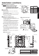
Pre-installation checks
Input Power: 120 Vac Single-phase is used.
Using the incorrect power supply may cause fi res, electric shocks or malfunctions.
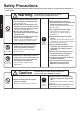
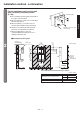
■ Checking the installation environment
Do not install the unit in the following types of locations.
(This may cause malfunctions.)
Outdoors Locations where the temperature could be lower than 32F (0C).
Locations where there is a lot of dust.
Locations where the temperature could be higher than 104F (40C).
Locations where there is a lot of condensation. Locations where salt damage may occur.
Locations where the unit is in direct or strong sunlight (may cause the sensor to malfunction).
In vehicles (including ships and airplanes)
Locations where corrosive, neutral or reductive gasses are present.
(This may shorten the working life of the unit and/or cause malfunctions.)
Near food or tableware Locations where the unit may come into direct contact with water.
Kitchens
(Where there is a risk of water splashing.)
Rooms that have a sterilization basin, swimming pools and baths.
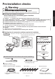
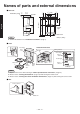
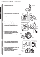
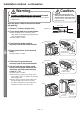
■ Checking the unit, accessories and items required for installation
※ Shaded areas in the fi gure indicate antibacterial material (excluding outlet nozzle areas).
Main unit
Air fi lter
Open
Lid
Drain tank
How to open/close the front cover
(refer to Page 13)
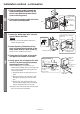
Mounting screws 7
(5×30 Type 1 tapping screws)
Installation panel 1
Cord clip mounting screw
(4 × 14)
1
Cord clip
1
Screwdriver Pen
Screw anchor
7 Wall reinforcement
※ To mark position to insert metal
screw plugs in the wall.
※ Use on concrete walls ※ Reinforces walls made of
materials other than concrete.
■ Prepare if required
※ Not needed if the internal wiring is
complete.
Single wire for internal wiring
(Cable core: between 2.0mm² and 3.0mm²)
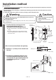
Warning
Front cover
Unit
Recommended tools and hardware to be used for installation
Accessories