
Installation manual

English
− NA - 4 −
6
7
/
16
"
(163)
7
1
/
2
"(190)
18
7
/
8
"(480)
9
7
/
8
"(251.5)
5
7
/
16
"(138.5)
5
15
/
16
"(150)
8
7
/
16
"(215)
9
7
/
8
"(250)
"3
15
/
16
(100)
"1
1
/
4
(31)
"2
1
/
16
(52)
"1
9
/
16
(40)
"6
11
/
16
(170)
"
1
/
8
(28)
"
1
/
16
(2)
1
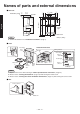
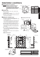
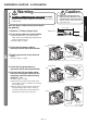
Names of parts and external dimensions
■ Main unit
■ Front
Installation panel
Air fi lter
Power
light
Drain tank
Unit (in. (mm))
Confi rm the details in the "Installation conditions" (Page 5).
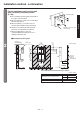
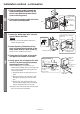
Power light
Front
cover
Nozzle
Sensor
Hand
drying
area
Lid
Drain tank
Water
receiver
area
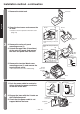
Inside the front cover
Air fi lter
Setting switches
Front cover Open
Sensor light
Sensor
switch
Heater light
Heater
switch
Power light
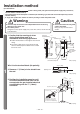
■ Rear
Power cord hole
Main unit
Open the front cover while referring to "How to open/close the front cover" (Page 13).
Please refer to "Turning the heater on" (Page 14) while turning the heater on/off.
Please refer to "Turning the sensor off before maintenance" (Page 15) while turning the sensor on/off.
NOTE
NOTE