
Installation manual

English
− NA - 6 −
"2
1
/
16
(52)
"5
1
/
2
(140)
"5
5
/
8
(143)
"1
9
/
16
(40)
"5
15
/
16
(150)
9
7
/
8
"(251.5)
5
7
/
16
"(138.5)
"
7
/
8
(22)
4
15
/
16
"
(125)
1
/
2
"
(12)
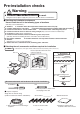
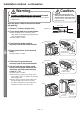
Installation method
For confi rmation
□ Input Power: 120 Vac Single-phase
power is being used (using the incorrect power supply may cause fi res,
electric shocks or malfunctions).
□ The ground fault circuit interrupter is attached (not attaching a ground fault circuit interrupter may result in
electric shocks).
□ A single wire (cable core: 2.0mm² or 3.0mm²) is being used for the power cable.
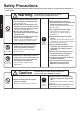
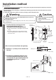
Warning
This hand dryer must have its own independent branch circuit using
AWG #12 or #14 copper wire.
Use 120 Vac power.
Using the incorrect power supply may cause fi res, fumes, electric shocks
or malfunctions.
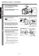
Caution
Do not install when the unit (power
cable) is electrifi ed.
Doing so may result in electric
shocks.
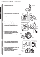
1
1. Confi rm that the severing of wires
during fi xed wiring work is in
accordance with wiring regulations.
Follow the illustration on the right for the internal
wiring.
The power cable forces out the main unit and
does not allow proper installation if the conduit
box is not used.
Wire it to the terminal block. (No polarity)
2. Remove
9
/
16
"(15mm) of wire sheath from
the end.
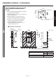
3. Position the installation panel on wall
so that the back electrical inlet can be
connected to the pre-installed electrical
conduit/tubing with the
1
/
2
" (16mm)
connector.
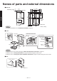
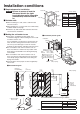
Unit (in. (mm))
Unit (in. (mm))
Unit (in. (mm))
Terminal block
Power cord hole (rear)
Unit external shape
Mounting
hole position
below the
unit
■
Single wire
Electrical
Conduit/Tubing
1
/
2
"
Connector
1
/
2
" Connector
Tighten to connect the
installation panel and
electrical conduit/tubing.
Back Electrical Inlet
39
9
/
16
"(1004.5)
- 43
1
/
2
"(1104.5)
min.
6
13
/
16
"(173)
min.
12
7
/
8
"(327)