
Installation manual

English
− NA - 9 −
Installation method - continuation
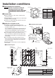
L
N
4
15
/
16
"
(125)
1
/
2
"
(12)
5
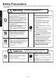
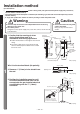
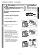
Warning
Input Power: 120 Vac Single-phase is used.
Using the incorrect power supply may cause fi res, electric shocks
or malfunctions.
Caution
Make sure that the main unit
does not fall as the base is not
attached to the wall with screws.
Injuries may be caused if the unit
falls off the wall.
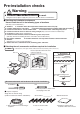
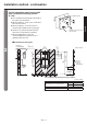
Wire the power cable to the terminal block.
(No polarity)
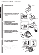
1. Remove
1
/
2
"(12mm) (single wire).
2.
Fix the power cable to the terminal block.
When stranded wire is used for the power
cable, attach an insulated ring tongue terminal
using an appropriate tool.
Proper torque is 1.5N·m
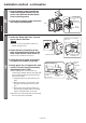
3. Check that the power cable is
securely fi xed to the terminal block.
4. Fix the ground wire to the terminal
block.
Proper torque is 1.5N·m
5. Check that the ground wire is
securely fi xed to the terminal block.
6. Use the cord clip mounting screw
hole to fi x the power cable with the
accessory cord clip and mounting
screw (4 × 14).
Proper torque is 1.5N·m
Fix it where the external wire sheath of the
power cable is when it is fixed in the cord clip
mounting position.
Do the wiring so that the power cable goes
through the right side of the circuit case.
The main unit panel may not be able to be
attached if it is above the circuit case.
Terminal block
Terminal block
Base
Circuit case
Power cable
Power cable
Screw
Screw
Power
cable
Power
cable
Ground wire
Ground wire of
installation panel
Ground wire of
installation panel
Ground
wire
Base
Circuit case
■
Single wire
Unit (in. (mm))
Base
Cord clip
mounting
screw hole
Circuit case
Power cable
Cord clip
mounting screw
(4×14)
(Accessory)
Cord clip
(Accessory)