
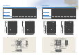
Specifications


23 24
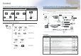
Definition of Symbols
M1: Motor for exhaust fan CN1: Connector
(
Transformer primary
)
M2: Motor for supply fan CN2: Connector
(
Transformer secondary
)
C: Capacitor CN5: Connector
(
Thermistor
)
GM: Motor for By-pass operation CN6: Connector
(
Microswitch
)
LS: Microswitch CN7: Connector
(
Motor for By-pass operation
)
TH1: Thermistor for outside air TAB3: Tab connector(Fan motor)
TH2: Thermistor for return air TAB5: Tab connector
(
Fan motor
)
SW1: Switch
(
Main/Sub change
)
CN9: Connector
(
Fan motor
)
SW2, 5: Switch
(
Function selection
)
CN10: Connector
(
Fan motor
)
TM1: Terminal block
(
Power supply
)
CN16: Connector
(
High/Low/By-pass switch
)
TM2: Terminal block
(External control input)
CN32: Connector
(
Remote control selection
)
TM3: Terminal block
(
Monitor output
)
SA1: Address setting rotary switch
(
10 digit
)
TM4 :
Terminal block
(
Transmission cable and monitor output
)
SA2: Address setting rotary switch
(
1 digit
)
TB5 : Terminal block
(
M-NET Transmission cable
)
SYMBOL : Indicates terminal block.
TAB1,TAB2
: Connector(Power supply)
: Connector.
TR1: Control circuit transformer
: Board insertion connector or fastening
X10,X11,X12
: Relay contact
connector of control board.
Wiring Diagrams
LGH-15RX5 to 100RX5
BLACK
BLACK
LS
LS
BLACK
BLACK
RED
WHITE
TR3
RED
WHITE
TR2
x201
x202
x203
x101
x102
x103
M
M
M
1
2
1
M
2
EXHAUST
SUPPLY
EXHAUST
FAN MOTOR
FAN MOTOR
FAN MOTOR
SUPPLY
FAN MOTOR
C
C
C
C
cable
transmission
M-NET
MELANS
(non-polar)
Mr.Slim
output 7 , 8
Malfunction monitor
monitor output 6 , 7
By-pass or Delay2
Sheild Wire
12V or 24V DC
BROWN
RED
TM4
CN16
10
876123
CN5
1
2
9
AB
S
X10
CN32
X11X12
Isolator
TAB2
TAB1
CN9
CN10
TAB5
TAB3
TM3 TB5
Transmission
cable
60DR-E
PZ-
BROWN
TM2
ORANGE
ORANGE
ORANGE
ORANGE
TH2(RA)
TH1(OA)
SW1
SW5
SW2
SA1
SA2
BLACK
GREY
YELLOW
ORANGE
WHITE
BLUE
BLUE
RED
BROWN
BROWN
BLUE
CN7
CN2
CN1
TM1
monitor output
Operation or Delay1
PE
N
N
L
L
24VDC
2A
5VDC
100mA
MAX 240VAC 2A MIN 220VAC 100mA
(non-polar)
TR1
BROWN
BLACK
GREY
YELLOW
YELLOW
GREY
BLACK
BROWN
WHITE
BLUE
ORANGE
RED
RED
ORANGE
BLUE
WHITE
31
Unchanged a-conntact
External control input
A
2nd or later main units
cable
transmission
M-NET
S
B
TB5(M-NET)
Sheild Wire
TM4
(PZ-60DR-E)
2nd remote controller
installable)
(*1)
Optional Remote controller
(Max.2 remote controllers
PZ-41SLB-E and PZ-52SF-E cannot
be used when using PZ-60DR-E
(*1)
5VDC 100mA
MIN 220VAC 100mA
24VDC
1A
MAX 240VAC 1A
transmission wire to , on TB5 terminal
B
A
2
1
of TM4 terminal block,and connect M-NET
is used as the M-NET System ,connect it to
block.
*When the optional Remote Controller PZ-60DR-E
GM
MG
GM
MG
x103
x102
x101
x203
x202
x201
2
1
GREEN/YELLOW
POWER SUPPLY
220-240V 50Hz
CN16
(Unchanged a-conntact)
RED
BROWN
YELLOW
ORANGE
GREEN
HI
LO
BY-PASS
With this product, the wiring installation method will
vary according to the design of the system.
Perform electrical installation to meet local electrical regulations.
.
Always use double insulated PVC cable for the transmission cables.
.
Wiring work must be performed by qualified professionals.
.
All supply circuits must be disconnected before obtaining access to the terminal devices.
NOTE 1.TM1, TM2, TM3, TM4, TB5 shown
in dotted lines are field work.
2.Isolator should be provided by the customer.
3.Be sure to connect the grounding wire.
*Attention
M
CC
(*2) LGH-200RX5 has 2
capacitors per mortor
as following drawing.
(*2)
(*2)
(*2)
(*2)
2nd remote controller (Max.2remote controllers installable cable)
2nd LOSSNAY unit (Up to max 15 units)
(*1)
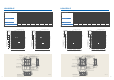
LGH-150RX5 and 200RX5
Definition of Symbols
M1: Motor for exhaust fan
X10,X11,X12
:Relay contact
M2: Motor for supply fan
X101,X102,X103:
Relay Supply fan speed control
C: Capacitor
X201,X202,X203:
Relay Exhaust fan speed control
GM: Motor for By-pass operation CN1: Connector (Transformer primary)
LS: Microswitch CN2: Connector (Transformer secondary)
TH1: Thermistor for outside air CN5: Connector (Thermistor)
TH2: Thermistor for return air CN6: Connector(Microswitch)
SW1: Switch (Main/Sub change) CN7: Connector (Motor for By-pass operation)
SW2, 5: Switch (Function selection) CN9: Connector (Fan motor)
TM1: Terminal block (Power supply) TAB3: Tab connector (Fan motor)
TM2: Terminal block(External control input) TAB5: Tab connector (Fan motor)
TM3: Terminal block (Monitor output) CN9: Connector (Fan motor)
TM4: Terminal block CN10: Connector (Fan motor)
(Transmission cable and monitor output) CN16: Connector(High/Low/By-pass switch)
TB5: Terminal block (M-NET Transmission cable) CN32: Connector (Remote control selection)
TAB1,TAB2: Connector(Power supply) SA1: Address setting rotary switch (10 digit)
TR1
: Control circuit transformer SA2: Address setting rotary switch (1 digit)
TR2,TR3: By-pass operation transformer SYMBOL : Indicates terminal block.
Board insertion connector or fastening
connector of control board.
*Specifications may be subject to change without notice.
*Specifications may be subject to change without notice.
POWER SUPPLY
220-240V 50Hz
2
1
TB5(M-NET)
(*1)
Optional Remote controller
AB
S
(PZ-60DR-E)
*When the optional Remote Controller PZ-60DR-E
cable
(non-polar)
24VDC
2A
5VDC
100mA
MAX 240VAC 2A MIN 220VAC 100mA
L
L
N
N
M
1
M
2
PE
monitor output
Operation or Delay1
LS
TR
TM1
CN1
CN2
CN7
BLUE
BROWN
YELLOW
RED
BROWN
RED
BLUE
BLUE
EXHAUST
FAN MOTOR
SUPPLY
FAN MOTOR
WHITE
ORANGE
YELLOW
GREY
BLACK
C
C
SA2
SA1
SW2
SW5
SW1
CN6
ORANGE
ORANGE
TH1(OA)
TH2(RA)
ORANGE
ORANGE
ORANGE
ORANGE
TM2
BROWN
PZ-
60DR-E
Transmission
TB5
TM3
TAB3
TAB5
CN10
CN9
TAB1
TAB2
Isolator
X12 X11
CN32
X10
S
BA
9
2
1
CN5
321678
10
CN16
TM4
RED
GREEN/YELLOW
BROWN
output 7 , 8
Malfunction monitor
monitor output 6 , 7
By-pass or Delay2
MAX 240VAC 1A
12V or 24V DC
Mr.Slim
(non-polar)
2nd remote controller (Max.2remote controllers installable cable)
2nd LOSSNAY unit (Up to max 15 units)
MELANS
cable
transmission
M-NET
Sheild Wire
24VDC 1A
MAX 240VAC 1A
5VDC
100mA
MIN 220VAC 100mA
Unchanged a-conntact
13
External control input
TM4
(Max.2 remote controllers
2nd remote controller
Sheild Wire
cable
transmission
M-NET
2nd or later main units
installable)
(*1)
PZ-41SLB-E and PZ-52SF-E cannot
be used when using PZ-60DR-E
is used as the M-NET System ,connect it to
of TM4 terminal block,and connect M-NET
transmission wire to , on TB5 terminal
block.
1
2
AB
GM
CN16
(Unchanged a-conntact)
HI
LO
EXTRA-LO
BY-PASS
M
CC
(*2) LGH-100RX5 has 2
capacitors per mortor
as following drawing.
(*2)
(*2)
(*1)
With this product, the wiring installation method will
vary according to the design of the system.
Perform electrical installation to meet local electrical regulations.
.
Always use double insulated PVC cable for the transmission cables.
.
Wiring work must be performed by qualified professionals.
.
All supply circuits must be disconnected before obtaining access to the terminal devices.
NOTE 1.TM1, TM2, TM3, TM4, TB5 shown
in dotted lines are field work.
2.Isolator should be provided by the customer.
3.Be sure to connect the grounding wire.
*Attention
BROWN
RED
ORANGE
YELLOW
GREEN