ADVANCED AND EVER ADVANCING 2010 DEHUMIDIFIER SERVICE MANUAL Model MITSUBISHI ELECTRIC No.MJW-10010 MJ-E15BX-S1-IT Sold from 2010 CONTENTS 1. 2. 3. 4. 5. 6. 7. 8. 9. 10. 11. 12. 13. 14.
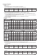
1. Product specifications Mode MJ-E15BX-S1-IT Electrical characteristics Performance Item Dehumidifying capacity 15.0 (30°C room temperature, 80% relative humidity) (liters/day) Operating noise High 49 levels(dB) Low 39 Power supply (phases,V,Hz) Single phase, 220-240V, 50Hz Power consumption (W) 290 Operating current (A) 1.4 Starting current (A) 5.
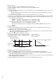
142.5 568 205 2. Outer Dimensions 20.5 390 205 3. Names and Functions of Parts Control Panel z CHILD LOCK lamp Lights while child lock is active. z CHILD LOCK Switch To lock/unlock the switch, press the switch for at least 3 seconds. z Tank FULL lamp The lights up to warn that the water tank is full. z DEFROST lamp Lights during defrosting operation. z DRYING INSIDE lamp z Flashes during the drying inside operation. z Lights when the drying inside operation is waiting to begin.
Front Back Air intake Control panel Main air outlet Handle Louvre Filter cover Back air outlet Sensor Do not cover. Silver ion sterilizing and deodorizing filter Power plug Accessory Wheel (4) z Silver ion sterilizing and deodorizing filter Tank Hereafter referred to as simply “sliver ion filter.” Tank lid The silver ion filter is supplied with the unit at the time of purchase. Set before using the unit.
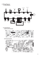
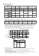
4. Wiring Diagram 1) Wiring Diagram Tube temperature thermistor Power plug Run capacitor Solenoid valve P3 P6 Compressor P1 P2 P15 Floating element SW P12 P11 Cool air damper Power/control board P7 P8 Warm air motor Cool air motor P31 TH P20 P21 P32 HUM.
5.
Laundry Operation 1. HIGH ① Control Summary (a) Dehumidifying operates continuously regardless of the humidity. (b) The constant compressor, cool air and warm air fans operate continuously. Target part Compressor Cool air fan Warm air fan Solenoid valve Louvre Damper Operation ON Rank control Rank control OFF Operation mode Dehumidifying position ② Laundry operations are disabled in the following cases. (a) When the LAUNDRY switch is pressed, it switches to LAUNDRY (NORMAL) operation.
② Startup conditions (a) When operation is on while LAUNDRY operations are selected (b) When LAUNDRY operations are selected by operating the LAUNDRY switch ③ Stopping condition 1 (a) Average humidity and temperature are measured 30 minutes after starting LAUNDRY operations, and every 10 minutes from then on. (Average humidity and temperature updates are performed at the same time as humidity measurements. Once every 15 seconds) (b) A shows the average temperature when the average humidity is 50% or less.
Dehumidifying operation 1.
2. Low Operation ① Control Summary (a) Dehumidifying operates continuously regardless of the humidity. (b) The constant compressor, cool air and warm air fans operate continuously. (c) By reducing the rank of the blower fan compared to high operation, the dehumidification function is decreased during operation.
3. COOL AIR/VARY Operation ① Control Summary (a) Dehumidifying operates continuously regardless of the humidity. (b) The constant compressor, cool air and warm air fans operate continuously. (c) Perform cool air operation by placing the damper position in cool air mode. (d) Control fluctuations by changing the cool air fan rank level by time. ② Change the cool air/warm air fan rank as follows. ③ When the room temperature is 36˚C or more, the warm air fan rank is fixed at rank 5.
DRYING INSIDE operation ① Control Summary (a) Prevents the growth of mildew by drying the moisture accumulated on the heat exchanger when the dehumidifier is off. (b) DRYING INSIDE operation does not depend on a full water level to operate. (c) The following operations are performed during DRYING INSIDE operation.
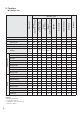
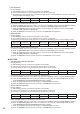
Blower fan rank Cool air (EVA) Fan rank Air Amount [m3/min] Rotation speed [rpm] 1 0.9 780 2 1.0 850 3 1.0 890 4 1.1 980 5 1.3 1,100 6 1.3 1,100 7 1.4 1,200 8 1.4 1,200 Fan rank Air Amount [m3/min] Rotation speed [rpm] 1 1.8 738 2 1.9 780 3 2.4 940 4 2.9 1,100 5 3.0 1,150 6 2.9 1,100 7 2.6 1,000 8 2.6 1,000 Warm air (COND) * The amount of air and the rotation speed values are standards.
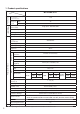
Swing ON Damper (Blowing route position) Drying inside lamp Buzzer Louvre Swing OFF Tank full lamp Float switch Tube temperature Solenoid valve Warm air fan Cool air fan Compressor Mode lamps Operation Max 3minutes Dehumidifying low Dehumidifying high CLOSE OFF OPEN OFF ON OFF ON High Laundry SW Dehumidifying position Laundry SW ON/OFF Auto Dehumidifying Dehumidifying SW SW OFF ON Stop Close Open at 90° OFF ON OFF ON ON 0˚C 12˚C OFF OFF ON OFF ON OFF ON OFF ON OFF O
Swing ON Swing OFF Damper (Blowing route position) Drying inside lamp Buzzer Louvre Tank full lamp Float switch Tube temperature Solenoid valve Warm air fan Cool air fan Compressor Mode lamps Operation ON CLOSE OFF OPEN OFF ON OFF ON OFF ON OFF ON OFF ON ON 0˚C 12˚C OFF OFF ON OFF ON OFF ON OFF ON OFF ON 120 seconds 40 minutes elapsed Start defrost count Start defrosting operation Tank full detection Depending on the mode 3 seconds Drying inside ON Each mode Stop
7.
8. Technical points The amount of dehumidifying becomes less in winter. When the temperature and humidity are low, the amount of water collected is decreased. In winter, because the temperature is lower than in summer, the effect of the dehumidifier is greatly reduced as shown in the graph below. Although only a little water collects in the tank, this is not a malfunction. Dehumidification capacity (L/day) When the humidity is 80% and the value is HIGH 15 Temp. Temp.
9. Troubleshooting Procedure 1) Troubleshooting flowchart The unit does not operate Start Abnormal Check AC power supply Restore AC power supply Normal Has the fuse blown out? Blown Replace fuse Not blown OFF Is the float switch turned on? Mechanical check ON • Correct defects. • Replace the switch if defective. Control board connector check With the power plug removed from the receptacle, remove and insert each connector two to three times to improve its contact.
A Step 3 Does the compressor operate? (NO if stalled) *The compressor does not operate for 3 minutes after turning the power ON or OFF. NO Is there an overcurrent? (Surface is hot) YES Replace compressor NO Check connectors YES Is the continuity of the motor protector no good? (Normal: CLOSE; Malfunction: OPEN) Replace motor protector *Check when there is no current and the unit is at room temperature.
2) Key Component Check Procedures Component name Tube temperature sensing thermistor P15 Room temperature and humidity sensor board Testing procedure Detach the connector and measure the resistance using a multimeter (component temperature: 10°C to 30°C). Normal Abnormal Between P15 pins: 8.0kΩ to 20.8kΩ Open or shorted Detach the connector and measure the resistance using a multimeter (component temperature: 10°C to 30°C).
3) Error Indications and Corrective Actions Indication (Timer display) Error (failure) Corrective action E0 P31, 32 connector out of position Room temperature thermistor blowout E1 Room temperature thermistor short Room temperature and humidity sensor board failure E7 P15 connector out of position Tube temperature thermistor blowout E8 Tube temperature thermistor short Tube temperature sensor failure A1 Microprocessor failure RAM error Replace the main board.
(2) LED monitor display ● Start Press the LAUNDRY switch and the DEHUMIDIFYING switch 4 times together when the power is off. Turn on the power within 2 seconds. ● Mode select Use the OFF timer switch to change the diagnostic modes (0 to 8). ● End Turn the power off.
10. Troubleshooting z For the symptoms listed below, refer to the remedies listed right. Symptom Cause/Remedy The unit blows warm air z Air passed through the re-heating coil is warm. z Unlike an air conditioner, the unit is not capable of cooling a whole room. Using the unit in a closed room will instead cause the room temperature to rise. z When the unit is set to COOL AIR/VARY or COOL AIR/LOW, warm air is blown from the back air outlet.
Symptom The operating sound is loud The operating noise is loud/ reverberates The unit makes noises The unit produces an odour The operating sound suddenly increases in volume The wind sound changes in volume The unit produces a simmering sound The unit makes a gentle clinking or rattling sound The unit produces a buzz that sounds intermittently (or the compressor does not activate) Cause/Remedy z Since the unit uses two fans and two motors in addition to the cool air function, the operating sound beco
11. Maintenance Maintenance Do not use detergents, cleaning agents for heat exchange equipment, abrasive powders, chemically treated dusters, gasoline, benzene, thinners or other solvents, as they can damage the unit or the water tank, which may result in leakage. Once Every Two Weeks Silver Ion Filter, Air Intake, and Sensor Clogging with dust and the like reduces the effectiveness of the dehumidifying. Clean once every two weeks.
Once Every Three Months Silver Ion Filter (Soak in Water) Soaking the silver ion filter in water enables you to remove fine dust and odor from the silver ion filter. Press the POWER switch to turn off the power, wait until the blower fan stops rotating (approximately 2 minutes) before unplugging the power cord. Soak the silver ion filter in 3 water. Soak in cool to lukewarm water for about 30 minutes. 1 Remove the filter cover.
Maintenance (cont.) Replacement Parts The silver ion filter becomes depleted over time. Replace it when necessary. Cleaning Water tank · Main unit Wipe with a soft cloth. Floating element Do not remove or dismantle. Replacing the silver ion filter Although the silver ion filter lasts roughly 2 years, replace it when: z You have soaked the filter 8 times. z The silver ion filter has turned brown due to cigarette smoke or black with dust.
12. Disassembly and Reassembly Hints 1. Removing the water tank Step 1) Pull out the tank. Tank 2. Removing the filter cover and rear case Step 1) Hold the filter cover tabs, pull the filter cover (See Figure 1) toward you, and remove. 2) Remove the special screws (2), left and right case setscrews (right:2, left:1) and the rear case Pic. 1 (See Pic. 1) setscrews (2). 3) Detach the catches (5 points on the right and Left and right left), and remove the right and left cases.
4. Removing the control board Pic. 1 <> Step 1) Remove the water tank, the left and right cases, the rear case, and the front case following the steps in sections 1 to 3 above. 2) Remove each connector (P20, P21, P11, P10, and P9). 3) Remove the top case setscrews (4), and remove the top case. (See Pic. 1) 4) Remove the operation control board setscrews (4), and remove the operation control board. Top case setscrews ※ Pic. 2 Operation control board Top case Pic.
5. Removing the blower fan assembly Step 1) Remove the water tank, the side case, the front case, and the rear case following the steps in sections 1 to 4 above. 2) Remove each connector (8) from the power/ control board, and remove the power/control board box assembly. 3) Detach the catch on the drain EVA, and remove the fan assembly. (See Pic. 1) Pic.
6. Removing the drain pan assembly Pic. 1 Step 1) Remove the water tank, the front case, the rear case, the left and right cases, and the blower fan assembly following the steps in sections 1 to 5 above. (See Pic. 1) 2) Remove the drain EVA setscrews (2). 3) Detach the catches (right, left, and center: 1 point each) on the drain pan and the drain EVA, and remove the drain EVA while lifting the heat exchanger from the main unit.
13.
Model MJ-E15BX-S1-IT Parts List [Case and tank structural relationship] Notes: 1. Circled reference numbers indicate performance parts. 2. New parts and the parts that are used only with these models lack compatibility. and are of critical importance for sustaining safety and performance. Use 3. Those parts that are marked by specified parts at replacement. 4. When ordering parts without part numbers, use the design number. The order may take a while to process.
MJ-E15BX-S1-IT Model Structural Disassembly Diagram [Case and tank structural relationship] D F 126 128 131 H 127 E B 132 H G 129 C B 130 A 36
Model MJ-E15BX-S1-IT Parts List [Case and tank structural relationship] Notes: 1. Circled reference numbers indicate performance parts. 2. New parts and the parts that are used only with these models lack compatibility. are of critical importance for sustaining safety and performance. Use and 3. Those parts that are marked by specified parts at replacement. 4. When ordering parts without part numbers, use the design number. The order may take a while to process.
MJ-E15BX-S1-IT Model Structural Disassembly Diagram [Case and fan structural relationship] 215 218 220 219 216 217 222 A 221 224 223 225 209 229 227 236 212 226 233 228 229 211 A 230 215 234 235 232 210 231 208 213 205 206 201 214 204 38 203 202 207
Model MJ-E15BX-S1-IT Parts List [Case and fan structural relationship] Notes: 1. Circled reference numbers indicate performance parts. 2. New parts and the parts that are used only with these models lack compatibility. and are of critical importance for sustaining safety and performance. Use 3. Those parts that are marked by specified parts at replacement. 4. When ordering parts without part numbers, use the design number. The order may take a while to process.
MJ-E15BX-S1-IT Model Structural Disassembly Diagram [Case and fan structural relationship] D F E B A G H C 40
Model MJ-E15BX-S1-IT Parts List [Case and fan structural relationship] Notes: 1. Circled reference numbers indicate performance parts. 2. New parts and the parts that are used only with these models lack compatibility. are of critical importance for sustaining safety and performance. Use and 3. Those parts that are marked by specified parts at replacement. 4. When ordering parts without part numbers, use the design number. The order may take a while to process.
MJ-E15BX-S1-IT Model Structural Disassembly Diagram [Drain pan components] 301 A 316 302 315 313 314 308 303 311 312 309 310 B 304 305 307 306 42
Model MJ-E15BX-S1-IT Parts List [Drain pan components] Notes: 1. Circled reference numbers indicate performance parts. 2. New parts and the parts that are used only with these models lack compatibility. and are of critical importance for sustaining safety and performance. Use 3. Those parts that are marked by specified parts at replacement. 4. When ordering parts without part numbers, use the design number. The order may take a while to process.
MJ-E15BX-S1-IT Model Structural Disassembly Diagram [Heat exchanger components] 403 404 416 417 418 421 405 413 423 411 406 A 401 426 407 408 414 410 415 402 412 419 420 423 422 D 422 B 424 C 409 425 44
Model MJ-E15BX-S1-IT Parts List [Heat exchanger components] Notes: 1. Circled reference numbers indicate performance parts. 2. New parts and the parts that are used only with these models lack compatibility. and are of critical importance for sustaining safety and performance. Use 3. Those parts that are marked by specified parts at replacement. 4. When ordering parts without part numbers, use the design number. The order may take a while to process.
14. Precautions Precautions The following diagrams indicate circumstances where danger can result from mishandling the unit. WARNING Mishandling may result in fatal or serious injuries. CAUTION Mishandling may result in injuries or damage to your home or property, etc. Meanings of the graphic symbols used in this manual and on the unit are explained below.
CAUTION Do not cover an air outlet or air intake with laundry, cloth, curtain, etc. This results in poor ventilation and may cause heat generation/fire. Do not put vases or any other objects filled with water on the unit. Water may leak into the unit adversely affecting electric insulation and cause electric shock and/or fire by short-circuiting. Do not wash the unit with water. Do not use the unit where it is likely to come in contact with water.
Precautions (cont.) CAUTION Install the unit in a location where the floor is flat and stable. If the unit falls over, the water collected in the water tank may leak damaging surrounding objects and in turn result in fire or electric shock caused by an electrical leak. Before moving the unit always switch it off, unplug it and remove water from the water tank.
Issued in 2010.