SPLIT-TYPE, HEAT PUMP AIR CONDITIONERS October 2012 No.OCH525 SERVICE MANUAL R410A Outdoor unit [Model name] PUHZ-SW40VHA PUHZ-SW50VHA Note: • This manual describes only service data of the outdoor units. [Service Ref.
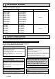
1 REFERENCE MANUAL INDOOR UNIT SERVICE MANUAL Model name EHST20C-VM6HB EHST20C-YM9HB EHST20C-VM6B EHST20C-YM9B EHST20C-VM6EB EHST20C-YM9EB EHST20C-VM6SB EHPT20X-VM2HB EHPT20X-VM6HB EHPT20X-YM9HB EHPT20X-VM6B EHPT20X-YM9B EHSC-VM6B EHSC-YM9B EHSC-VM6EB EHSC-YM9EB EHPX-VM2B EHPX-VM6B EHPX-YM9B ERSC-VM2B 2 Service ref. Service manual No. EHST20C-VM6HB.UK EHST20C-YM9HB.UK EHST20C-VM6B.UK EHST20C-YM9B.UK EHST20C-VM6EB.UK EHST20C-YM9EB.UK EHST20C-VM6SB.UK EHPT20X-VM2HB.UK EHPT20X-VM6HB.UK EHPT20X-YM9HB.
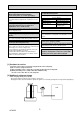
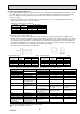
Use the following tools specifically designed for use with R410A refrigerant. Store the piping indoors, and both ends of the piping sealed until just before brazing. (Leave elbow joints, etc. in their packaging.) The following tools are necessary to use R410A refrigerant. If dirt, dust or moisture enters into refrigerant cycle, that can cause deterioration of refrigerant oil or malfunction of compressor.
[3] Service tools Use the below service tools as exclusive tools for R410A refrigerant. No. 1 Tool name Specifications Gauge manifold · Only for R410A · Use the existing fitting specifications. (UNF1/2) · Use high-tension side pressure of 5.3MPa·G or over. 2 Charge hose · Only for R410A · Use pressure performance of 5.09MPa·G or over. 3 Electronic scale 4 Gas leak detector · Use the detector for R134a, R407C or R410A. 5 Adaptor for reverse flow check · Attach on vacuum pump.
(2) Cautions for refrigerant piping work New refrigerant R410A is adopted for replacement inverter series. Although the refrigerant piping work for R410A is same as for R22, exclusive tools are necessary so as not to mix with different kind of refrigerant. Furthermore as the working pressure of R410A is 1.6 times higher than that of R22, their sizes of flared sections and flare nuts are different.
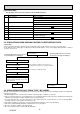
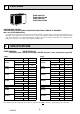
3 FEATURES PUHZ-SW40VHA PUHZ-SW40VHA-BS PUHZ-SW50VHA PUHZ-SW50VHA-BS CHARGELESS SYSTEM PRE-CHARGED REFRIGERANT IS SUPPLIED FOR PIPING LENGTH AT SHIPMENT Max. 10m (PUHZ-SW40/SW50) The refrigerant circuit with LEV (Linear Expansion Valve) and power receiver always control the optimal refrigerant level regardless of the length (10 m max. and 5 m min.) of piping. The additional refrigerant charging work during installation often causes problems. It is completely eliminated by chargeless system.
Rating conditions Nominal operating condition Heating (A7/W35) Outside air temperature (Dry-bulb) Outside air temperature (Wet-bulb) Water temperature (inlet/outlet) Heating (A7/W45) Outside air temperature (Dry-bulb) Outside air temperature (Wet-bulb) Water temperature (inlet/outlet) Heating (A2/W35) Outside air temperature (Dry-bulb) Outside air temperature (Wet-bulb) Water temperature (inlet/outlet) Heating (A2/W45) Outside air temperature (Dry-bulb) Outside air temperature (Wet-bulb) Water temperature (
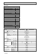
5 DATA 5-1. REFILLING REFRIGERANT CHARGE (R410A : kg) Piping length (one way) Service Ref. Initial 10m 20m 30m 40m 50m 60m 75m charged PUHZ-SW40VHA PUHZ-SW40VHA-BS 2.1 2.3 2.5 2.7 2.9 — — 2.5 PUHZ-SW50VHA PUHZ-SW50VHA-BS 2.1 2.3 2.5 2.7 2.9 — — 2.5 Additional charge is required for pipes longer than 10 m. 5-2. COMPRESSOR TECHNICAL DATA (at 20°C) Service Ref. PUHZ-SW40VHA(-BS) PUHZ-SW50VHA(-BS) Compressor model SNB130FGCM2 Winding Resistance ( ) U-V 0.64 U-W 0.
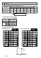
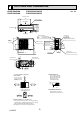
6 OUTLINES AND DIMENSIONS PUHZ-SW40VHA PUHZ-SW50VHA Unit : mm PUHZ-SW40VHA-BS PUHZ-SW50VHA-BS Installation bolt pitch 150 500 4-10×21 oval hole 40 365 32.5 300 Side air intake 330 Rear air intake Air discharge Terminal connections LeftPower supply wiring RightIndoor/Outdoor wiring 18 Handle for moving Handle for moving Service panel for charge plug 23 Connection for liquid pipe FLARE :6.35(1/4F) 440 155 10 90 300 43° Service panel 35° 600 Earth terminal 287.
WIRING DIAGRAM NAME SYMBOL Terminal Block P. B. R, S Motor for Compressor U, V, W Fan Motor IPM Solenoid Valve (Four-Way Valve) PFC High Pressure Switch CB1, CB2, CB3 High Pressure Sensor Thermistor N. F. LI, LO Thermistor NI, NO Thermistor <2-Phase Pipe> EI, E2, E3 Thermistor 52C Thermistor Thermistor C. B.
8 WIRING SPECIFICATIONS 8-1. FIELD ELECTRICAL WIRING (power wiring specifications) Outdoor unit model SW40, 50V ~/N (single), 50 Hz, 230 V 16 A 3 × Min. 1.5 3 × 1.5 (Polar) 1 × Min. 1.5 2 × 0.3 (Non-polar) Outdoor unit power supply Circuit rating Wiring Wire No.
9 REFRIGERANT SYSTEM DIAGRAM PUHZ-SW40VHA PUHZ-SW50VHA Unit : mm (inch) PUHZ-SW40VHA-BS PUHZ-SW50VHA-BS Stop valve (with service port) Refrigerant GAS pipe connection ø12.7(1/2F) High pressure sensor (63HS) Charge plug Solenoid valve (Four-way valve) Heat exchanger Thermistor TH7 (Ambient) Thermistor TH6 (2-phase pipe) Strainer #50 Thermistor TH3 (Liquid) Distributor High pressure switch 63H Thermistor TH4 (Discharge) Thermistor TH34 (Comp.
9-1. Refrigerant collecting (pump down) Perform the following procedures to collect the refrigerant when moving the indoor unit or the outdoor unit. 1 Supply power (circuit breaker). * When power is supplied, make sure that “CENTRALLY CONTROLLED” is not displayed on the remote controller. If “CENTRALLY CONTROLLED” is displayed, the refrigerant collecting (pump down) cannot be completed normally.
10 TROUBLESHOOTING 10-1. TROUBLESHOOTING Present and past error codes are logged and displayed on the control board of outdoor unit. Actions to be taken for service, which depends on whether or not the trouble is reoccurring at service, are summarized in the table below. Check the contents below before investigating details.
10-3. SELF-DIAGNOSIS ACTION TABLE Error Code Abnormal points and detection method None — (Note 1) Refer to indoor unit section for code P and code E. Judgment and action Case 1 No voltage is supplied to termi- 1 Check following items. nal block (TB1) of outdoor unit. a) Power supply breaker a) Power supply breaker is turned off. b) Connection of power supply terminal b) Contact failure or disconnecblock.
Error Code EA Eb Abnormal points and detection method Case Judgment and action Miswiring of indoor/outdoor unit connecting wire 1. Outdoor controller circuit board can automatically check the number of connected indoor units. Abnormal if the number cannot be checked automatically due to miswiring of indoor/outdoor unit connecting wire and etc. after power is turned on for 4 minutes. 2. Abnormal if outdoor controller circuit board recognizes excessive number of indoor units.
Error Code Abnormal points and detection method High pressure (High-pressure switch 63H operated) Abnormal if high-pressure switch 63H operated ( w ) during compressor operation. w SW40,50 (63H) : 4.15 MPa 63H: High-pressure switch U1 High discharging temperature (1) Abnormal if discharge temperature thermistor (TH4) exceeds 125: or 110: continuously for 5 minutes.
Error Code Abnormal points and detection method Open/short of outdoor unit thermistors 1 Disconnection or contact failure 1 Check connection of connector (TH3,TH6/ (TH3, TH6, TH7, and TH8) of connectors TH7) on the outdoor controller circuit board. Abnormal if open or short is detected Outdoor controller circuit Check connection of connector (CN3) on the during compressor operation. board: TH3, TH6/TH7 outdoor power circuit board.
Error Code Abnormal point and detection method Judgment and action Case To find out the details about U9 error, turn ON SW2-1, 2-2, 2-3, 2-4, 2-5 and 2-6 when U9 error occurs. Detailed To find out the detail history (latest) about U9 error, turn ON SW2-1, 2-2 and 2-6. codes Refer to 10-10. 01 02 04 U9 08 10 20 OCH525 Overvoltage error 1 • Increase in DC bus voltage to 420V 2 3 1 Check the field facility for the power supply. 2 Correct the wiring (U.V.W phase) to compressor.
Error Code Ud UE Abnormal points and detection method Judgment and action 1 Defective outdoor fan (fan Over heat protection motor) or short cycle of outAbnormal if liquid thermistor (TH3) detects door unit during cooling opera70: or more during compressor operation tion. 2 Defective liquid thermistor (TH3) 3 Defective outdoor controller board 1 Check outdoor unit air passage.
Error Code E0 or E4 E1 or E2 E3 or E5 Case Abnormal points and detection method Remote controller transmission error (E0)/signal receiving error (E4) 1 Abnormal if main or sub remote controller cannot receive normally any transmission from indoor unit of refrigerant address “0” for 3 minutes. (Error code : E0) 2 Abnormal if sub remote controller could not receive any signal for 2 minutes.
Error Code E6 Abnormal points and detection method Indoor/outdoor unit communication error (Signal receiving error) 1 Abnormal if indoor controller board could not receive any signal normally for 6 minutes after turning the power on. 2 Abnormal if indoor controller board could not receive any signal normally for 3 minutes. 3 Consider the unit as abnormal under the following condition.
Error Code Abnormal points and detection method Case Judgment and action Freezing/overheating protection is operating Overheating protection Abnormal if condensing temperature of pressure sensor (63HS) detects Tcond. °C or more and compressor operation frequency is less than or equal to 25 Hz. Detection is inoperative during defrosting.
10-4. TROUBLESHOOTING A flowing water sound or occasional hissing sound is heard. ■ These sounds can be heard when refrigerant and/or water is (are) flowing in the indoor unit or refrigerant pipe, or when the refrigerant and/or water is (are) chugging. Water does not heat or cool well. ■ Clean the filter of water piping. (Flow is reduced when the filter is dirty or clogged.) ■ Check the temperature adjustment and adjust the set temperature.
10-5. TROUBLESHOOTING BY INFERIOR PHENOMENA Phenomena 1. Remote controller display does not work. Factor 1DC12V is not supplied to remote controller. (Power supply display is not indicated on LCD.) 2DC12~15V is supplied to remote controller, however, no display is indicated. • “PLEASE WAIT” is not displayed. • “PLEASE WAIT” is displayed. Countermeasure 1 Check LED2 on indoor controller board. (1) When LED2 is lit. Check the remote controller wiring for breaking or contact failure.
Phenomena 7. Remote controller display works normally and the unit performs heating operation, however, the capacity cannot be fully obtained. Factor Countermeasure 1Linear expansion valve fault 1• Discharging temperature and indoor heat Opening cannot be adjusted well due to linear expanexchanger temperature does not rise. sion valve fault. Inspect the failure by checking discharging pressure. 2Refrigerant shortage • Replace linear expansion valve.
Symptoms: “PLEASE WAIT” is kept being displayed on the remote controller. Diagnosis flow Cause Inspection method and troubleshooting Check the display time of “PLEASE WAIT” after turning on the main power. 6 minutes or more How long is “PLEASE WAIT” kept being displayed on the remote controller? 2 minutes or less 2 to 6 minutes Are any error codes displayed on the remote controller? Check the LED display of the outdoor controller circuit board.
Symptoms: Nothing is displayed on the remote controller Diagnosis flow Cause LED display of the indoor controller board LED1 : LED2 : LED3 : Inspection method and troubleshooting Check the voltage between S1 and S2 on the terminal block (TB4) of the indoor unit which is used to connect the indoor unit and the outdoor unit. AC 198V to AC 264V? YES NO Check the voltage among L(L3) and N on the terminal block (TB1) of the outdoor power circuit board.
Symptoms: Nothing is displayed on the remote controller Diagnosis flow Cause LED display of the indoor controller board LED1 : LED2 : LED3 : or Inspection method and troubleshooting Check the voltage between S1 and S2 on the terminal block (TB4) of the indoor unit which is used to connect the indoor unit and the outdoor unit. NO AC 198V to AC 264V? YES Not lighting. Check the status of the indoor controller board LED3 display.
Symptoms: Nothing is displayed on the remote controller Diagnosis flow Cause LED display of the indoor controller board LED1 : LED2 : or LED3 : — Inspection method and troubleshooting Check the voltage of the terminal block (TB6) of the remote controller. DC 10V to DC 16V? YES • Defective remote controller • Replace the remote controller. NO Check the status of the LED2.
• Before repair Frequent calling from customers Phone Calls From Customers Unit does not operate at all. The operating display of remote controller does not come on. Unit cannot be restarted for a while after it’s stopped. Remote controller How to Respond Error code appears and blinks on the display of remote controller. Error code will be displayed if any protection devices of the air conditioner are actuated. What is error code? “PLEASE WAIT” is displayed on the screen. Wait around 2 minutes.
Phone Calls From Customers The room cannot be cooled or heated sufficiently. How to Respond Note Check the set temperature of remote controller. The outdoor unit cannot be operated if the set temperature is not appropriate. The outdoor unit operates in the following modes. COOL: When the set temperature is lower than the room temperature. HEAT: When the set temperature is higher than the room temperature. Check if filters are not dirty and clogged.
Phone Calls From Customers How to Respond Something is wrong with the blower….. Air blows out for a while after HEAT operation is stopped. This is not a malfunction. The blower is operating just for cooling down the heated-up air conditioner. This will be done within 1 minute. This control is conducted only when the HEAT operation is stopped with the electric heater ON. Something is wrong with the airflow direction…. The airflow direction is changed during COOL operation.
Phone Calls From Customers How to Respond Note A white mist is expelled from the indoor unit. This is not a malfunction. This may occur when the operation gets started in the room of high humidity. Water or moisture is expelled from the outdoor unit. Cooling; when pipes or piping joints are cooled, they get sweated and water drips down. Heating; water drips down from the heat exchanger.
Check method of DC fan motor (fan motor / outdoor controller circuit board) Notes · High voltage is applied to the connecter (CNF1, 2) for the fan motor. Pay attention to the service. · Do not pull out the connector (CNF1, 2) for the motor with the power supply on. (It causes trouble of the outdoor controller circuit board and fan motor.) Self check Symptom : The outdoor fan cannot turn around. Fuse check Check the fuse (F5) on outdoor controller board. Replace outdoor controller board (C.
10-8. HOW TO CHECK THE COMPONENTS 50 Low temperature thermistors • Thermistor (TH3) • Thermistor <2-phase pipe> (TH6) • Thermistor (TH7) Resistance (k ) 40 Thermistor R0 = 15k' ± 3% B constant = 3480 ± 2% Rt =15exp{3480( 0: 10: 20: 25: 15k' 9.6k' 6.3k' 5.2k' 1 1 )} – 273+t 273 30: 4.3k' 40: 3.
Linear expansion valve (1) Operation summary of the linear expansion valve • Linear expansion valve opens/closes through stepping motor after receiving the pulse signal from the outdoor controller board. • Valve position can be changed in proportion to the number of pulse signal.
(3) How to attach and detach the coil of linear expansion valve Linear expansion valve is separable into the main body and the coil as shown in the diagram below. Main body Coil Lead wire Stopper Hold the lower part of the main body (shown as A) firmly so that the main body does not move and detach the coil by pulling it upward. Be sure to detach the coil holding main body firmly. Otherwise pipes can bend due to pressure.
10-9. TEST POINT DIAGRAM Outdoor controller circuit board PUHZ-SW40VHA PUHZ-SW40VHA-BS PUHZ-SW50VHA PUHZ-SW50VHA-BS CNDM SW1 Forced defrost, detect history record reset, refrigerant address SW7 Demand control setting TEST POINT1 is high voltage.
Outdoor noise filter circuit board PUHZ-SW40VHA PUHZ-SW40VHA-BS PUHZ-SW50VHA PUHZ-SW50VHA-BS LI, NI Voltage of 230V AC is input. (Connect to the terminal block (TB1)) EI Connect to the earth E2 Connect to the earth E3 Connect to the earth CNAC1, CNAC2 230V AC (Connect to the outdoor controller circuit board (CNAC)) CN5 Primary current (Connect to the outdoor power circuit board (CN5)) LO, NO Voltage of 230V AC is output.
Outdoor power circuit board PUHZ-SW40VHA PUHZ-SW40VHA-BS PUHZ-SW50VHA PUHZ-SW50VHA-BS Brief Check of DIP-IPM and DIP-PFC W Usually, they are in a state of being short-circuited if they are broken. Measure the resistance in the following points (connectors, etc.). If they are short-circuited, it means that they are broken. 1. Check of DIP-IPM P2 - U , P2 - V , P2 - W , N2 - U , N2 - V , N2 - W 2.
10-10. FUNCTION OF SWITCHES, CONNECTORS AND JUMPERS (1) Function of switches Type of Switch Swich No. The black square ( ) indicates a switch position.
(2) Function of connector Types Connector Function Connector CN31 Emergency operation Action by open/ short operation Short Open Start Normal Effective timing When power supply ON Special function (a) Low-level sound priority mode (Local wiring) Unit enters into Low-level sound priority mode by external signal input setting. Inputting external signals to the outdoor unit decreases the outdoor unit operation sound 3 to 4 dB lower than that of usual.
The blinking patterns of both LED1 (green) and LED2 (red) indicate the types of abnormality when it occurs. Types of abnormality can be indicated in details by connecting an optional part ‘A-Control Service Tool (PAC-SK52ST)’ to connector CNM on outdoor controller board.
Indication Outdoor controller board LED1 (Green) LED2 (Red) Error Error Contents code +1 3 blinking 1 blinking Abnormality of comp.surface thermistor(TH34) U2 and discharging temperature (TH4) Abnormality of superheat due U7 to low discharge temperature 2 blinking Abnormal high pressure (High U1 pressure switch 63H operated.
[When optional part ‘A-Control Service Tool (PAC-SK52ST)’ is connected to outdoor controller board (CNM)] Digital indicator LED1 displays 2 digit number or code to inform operation condition and the meaning of error code by controlling DIP SW2 on ‘A-Control Service Tool’.
The black square ( ) indicates a switch position. SW2 setting ON Explanation for display Display detail Pipe temperature / Liquid(TH3) -40 – 90 -40 – 90 (When the coil thermistor detects 0°C or below, “–” and temperature are displayed by turns.) (Example) When -10°C; 0.5 secs. 0.5secs. 2 secs. 1 2 3 4 5 6 Unit : 10 Discharge temperature (TH4) 3 – 217 3 – 217 (When the discharge thermistor detects 100°C or more, hundreds digit, tens digit and ones digit are displayed by turns.
The black square ( ) indicates a switch position. ON 1 2 3 4 5 6 Pipe temperature / Liquid (TH3) on error – 40~90 occurring (When the coil thermistor detects 0°C or below, “–” -40 – 90 and temperature are displayed by turns.) (Example) When -15°C; 0.5 secs. 0.5secs. 2 secs.
The black square ( ) indicates a switch position. SW2 setting Explanation for display Display detail The number of connected indoor units ON Unit 0–4 (The number of connected indoor units are displayed.) Unit 1 2 3 4 5 6 Capacity setting display Displayed as an outdoor capacity code.
The black square ( ) indicates a switch position. Indoor setting temperature 17 – 30 ON Explanation for display Display detail SW2 setting Unit 17 – 30 °C 1 2 3 4 5 6 Pressure saturation temperature (T63HS) -39 – 88 ON -39 – 88 (When the temperature is 0°C or less, “–” and temperature are displayed by turns.) °C 1 2 3 4 5 6 Outdoor ambient temperature (TH7) -39 – 88 ON -39 – 88 (When the temperature is 0°C or less, “–” and temperature are displayed by turns.
The black square ( ) indicates a switch position. SW2 setting ON Explanation for display Display detail 180~370 (When it is 100V or more, hundreds digit, tens digit and ones digit are displayed by turns.
The black square ( ) indicates a switch position. Display detail Explanation for display LEV-A opening pulse on error occurring 0 – 480 0 – 480 (When it is 100 pulse or more, hundreds digit, tens digit and ones digit are displayed by turns.) (Example) When 130 pulse; 0.5 secs. 0.5secs. 2 secs.
The black square ( ) indicates a switch position. SW2 setting Display detail Explanation for display Unit Discharge superheat on error occurring SHd 0 – 255 0 – 255 (When the temperature is 100°C or more, hundreds digit, tens digit and ones digit are displayed by turns.) (Example) When 150°C; 0.5 secs. 0.5secs. 2 secs.
The black square ( ) indicates a switch position. Comp.surface temperature (TH34) -52 – 221 ON 1 2 3 4 5 6 -52 – 221 (When the comp.shell thermistor detects 100°C or more, hundreds digit, tens digit and ones digit are displayed by turns.) (Example) When 105°C; 0.5 secs. 0.5secs. 2 secs. 1 U9 Error details (To be shown while error call is deferred.
11 DISASSEMBLY PROCEDURE PUHZ-SW40VHA PUHZ-SW40VHA-BS OPERATING PROCEDURE 1. Removing the top panel, service panel, front panel and back panel (1) Remove the top panel fixing screws (4 × 10), one from the right and two from the left side, and detach the top panel. PUHZ-SW50VHA PUHZ-SW50VHA-BS PHOTOS Photo 1 Top panel Top panel fixing screws Back panel (2) Remove 1 service panel fixing screw (4 × 10) and detach the service panel by pulling it downward. (See Photo 2.
OPERATING PROCEDURE PHOTOS 3. Removing the electrical parts box (1) Remove the service panel. (See Photo 2) (2) Remove the top panel. (See Photo 1) (3) Remove the front panel. (See Photo 1) (4) Disconnect the indoor/outdoor connecting wire from terminal block. (5) Disconnect the connector CNF1, LEV-A and LEV-B on the controller circuit board. • CNF1 : Fan motor • LEV-A, LEV-B : LEV (6) Disconnect the pipe-side connections of the following parts.
OPERATING PROCEDURE PHOTOS 5. Removing the thermistor (TH7) (1) Remove the service panel. (See Photo 2) (2) Remove the top panel. (See Photo 1) (3) Remove the front panel. (See Photo 1) (4) Disconnect the connector TH7 (red) on the controller circuit board in the electrical parts box. (5) Loosen the clamp for the lead wire in the rear of the electrical parts box. (See Photo 6) (6) Pull out the thermistor (TH7) from the sensor holder.
OPERATING PROCEDURE PHOTOS 8. Removing the 4-way valve (1) Remove the service panel. (See Photo 2) (2) Remove the top panel. (See Photo 1) (3) Remove the front panel. (See Photo 1) (4) Remove the back panel. (See Photo 1) (5) Remove the electrical parts box. (See Photo 5) (6) Remove the 4-way valve (See Photo 9) (7) Recover refrigerant. (8) Remove the welded part of 4-way valve. Note 1: Recover refrigerant without spreading it in the air.
OPERATING PROCEDURE PHOTOS 12. Removing the compressor (MC) Photo 13 Thermistor Thermistor (1) Remove the service panel. (See Photo 2) (2) Remove the top panel. (See Photo 1) (TH4) (TH34) (3) Remove the front panel. (See Photo 1) Separator (4) Remove the back panel. (See Photo 1) (5) Remove the electrical parts box. (See Photo 5) (6) Remove the thermistor (TH4) and thermistor (TH34).
HEAD OFFICE : TOKYO BLDG., 2-7-3, MARUNOUCHI, CHIYODA-KU, TOKYO 100-8310, JAPAN cCopyright 2012 MITSUBISHI ELECTRIC CORPORATION Distributed in Oct. 2012 No.OCH525 Made in Japan New publication, effective Oct. 2012 Specifications are subject to change without notice.