
Service manual


9
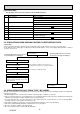
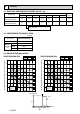
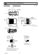
6 OUTLINES AND DIMENSIONS
PUHZ-SW40VHA PUHZ-SW40VHA-BS
PUHZ-SW50VHA PUHZ-SW50VHA-BS
Unit : mm
100 mm or more as long as
no obstacle is placed on the
rear and right-and-left sides
of the unit.
*1ޓIn the place where short cycle tends to occur,cooling and heating
ޓ capacity and power consumption might get lowered 10%. Air outlet
ޓ guide (optional PAC-SG58SG) will help them improve.
*2 If air discharges to the wall, the surface might det stained.
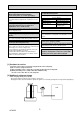
Please secure the unit firmly
with 4 foundation (M10) bolts.
(Bolts, washers and nut must
be purchased locally).
FOUNDATION BOLTS
Minimum installation space for outdoor unit
Free space around the outdoor unit
(basic example)
Piping and wiring connection can
be made from the rear direction only.
PIPING-WIRING DIRECTION
Handle for moving
Handle for
moving
18
69
10
600
300
287.5
800
Terminal connections
LeftPower supply wiring
RightIndoor/Outdoor wiring
Service panel
Earth terminal
Service panel
for charge plug
Connection for
liquid pipe FLARE :6.35(1/4F)
Connection for
gas pipe FLARE :12.7(1/2F)
Service port
183
440
23
90
155
35°
43°
6-:33 drain hole
2-:12 drain hole
70
45
400
500
347.4
226
0
43.6
155
152
74.3
0
60
118
0
284.3
Less than
<Foundation bolt height>
18mm
100mm or more
500mm or more
2 sides should be open in
the right,left and rear side.
*1
*2
*1
350mm or more
100mm or more
Basically open
Air discharge
4-10×21 oval hole
Side air intake
Rear air intake
32.5
40
330
300
365
150 500
Installation bolt pitch
FOUNDATION
OCH525