
Installation manual

- 6 -
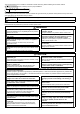
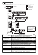
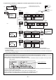
1. Standard configuration (using the AG-150A to control a system with 50 or fewer units of equipments)
* Address setting for each M-NET device (Addresses cannot be duplicated).
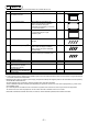
5 System Diagram
Address setting method Address
Indoor unit
Set the indoor unit you want to make the main unit in the same group to the minimum
address, then sequentially set the indoor unit addresses in the same group.
1~50
Outdoor unit Minimum indoor unit address in same refrigerant system + No.50 unit. 51~100
BC controller/OS controller
Outdoor unit address in same refrigerant system + No.1 unit.
However, for Sub-BC controller, the minimum indoor unit address that connects the
local refrigerant piping should be + 50.
52~100
K control side remote controller Same address as indoor unit main unit. 1~50
Mr. Slim Outdoor unit
Same address as indoor unit main unit. An M-NET adapter (sold separately) is required.
1~50
M-NET remote controller Set to the minimum indoor unit main address in the same group + 100. 101~200
Sub system controller Assign an address that equals the lowest group number plus 200. 201~250
DIDO controller
(PAC-YG66DCA)
Assign an arbitrary but unused address to the PAC-YG66DCA DIDO controller after
assigning an address to all units to be assigned an address between 1 and 50.
The number of controllable units depends on the number of channels used.
1~50
Pl controller (PAC-YG60MCA)
Assign an arbitrary but unused address to the PI controller after assigning an address
to all units to be assigned an address between 1 and 50.
1~50
Al controller (PAC-YG63MCA)
Assign an arbitrary but unused address to the AI controller after assigning an address
to all units to be assigned an address between 1 and 50.
1~50
MA remote controller Address setting is unnecessary. -
OA processing unit/LOSSNAY After setting all the indoor units, set an arbitrary but unused address. 1~50
K transmission converter Minimum address of K control indoor unit + 200. 201~250
Air To Water
Set the Air To Water you want to make the main unit in the same group to the minimum
address, then sequentially set the Air To Water addresses in the same group.
1~50
M-NET
LOSSNAY
TB7 TB3
ME
MA
K
TB7 TB3
MA
K
R2
213
13 15
TB7 TB3
MA MA
003
004
Indoor unit
Local remote controller
M-NET transmission line
K transmission line
MA remote controller line
The numbers in the
indicate the address No.
NOTE
* This diagram does not
show the AC power supply
wiring. Only the
configuration for the
transmission line is shown.
POWER (24VDC)
Centralized controller
Model:AG-150A
Power supply unit (optional)
Model: PAC-SC51KUA
LAN
M-NET
outdoor unit
BC controller
Group 3
Group 1 Group 2
M-NET
outdoor unit
Mr. Slim
Outdoor unit
Mr. Slim
Outdoor unit
M-NET adapter
Group 4
Group 5
K control
outdoor unit
Group 13 Group 15
K transmission converter
Model:PAC-SC25KAA
WT05368X08.fm Page 6 Thursday, March 17, 2011 9:21 AM