
Installation manual

- 7 -
1-1. M-NET wiring configuration
(1) Types and maximum allowable length of M-NET transmission cables
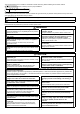
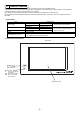
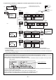
The wiring diagram below shows a sample M-NET transmission wiring for a CITY MULTI system.
The maximum total line distance (centralized control and indoor-outdoor transmission lines) for each M-NET system is expressed
in the formula below. Observe the maximum length to ensure proper signal transmission to and from the connected equipments
over the M-NET transmission line.
If the maximum line length is exceeded, the M-NET signals will be attenuated, resulting in communication error and control
failure.
a+b+d+e(f) ≤ 500m a+b+c+g ≤ 500m e(f)+d+c+g ≤ 500m
The local remote controller cable length should be 10 m or shorter. The part that exceeds the 10 m limit should be included in the
maximum total line length of 500 m.
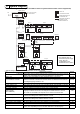
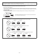
(A) Centralized control transmission line
The power supply distance for the centralized controller transmission line is expressed in the formula below.
This is the maximum length of the centralized control transmission line to which proper amount of power reaches. If the maximum
line length is exceeded, those equipments at the end of the transmission line may not receive enough power, resulting in
communication error and control failure.
a+b ≤ 200m a+b+c ≤ 200m
(B) Indoor-outdoor transmission line
The power supply distance for the indoor-outdoor transmission line is expressed in the formula below.
This is the maximum length of the indoor-outdoor transmission line to which proper amount of power reaches. If the maximum
line length is exceeded, those equipments at the end of the transmission line may not receive enough power, resulting in
communication error and control failure.
d+e(f) ≤ 200m g ≤ 200m
The length of the local remote controller cable that exceeds the 10 m limit should be included in the maximum total line length of
500 m and in the power supply distance of 200 m.
NOTES
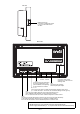
* Apply following precautions when using the K transmission converter (model PAC-SC25KAA; discontinued) and controlling the
M-NET model and K control model with the same controller.
Refer to the K transmission converter (PAC-SC25KAA) installation manual for details.
1 Centralized controller address
Always set the controller address to “000”.
2 Centralized controller function selects
Set the “K Converter Address” by using the “M-NET Settings” on the Initial settings screen.
3 Indoor unit address
Set all M-NET model indoor units from the No.1 unit, then set the K control model addresses.
Indoor unit No.1 unit ~M-NET indoor unit max. address> K control indoor unit minimum address ~50
4 K control model group No.
The minimum indoor address No. of that group becomes the group No. (Same for K control side local remote controller.)
5 The remote controller address does not need to be included in the K-control unit group settings.
NOTE
* Some types of units cannot be controlled from the AG-150A controller.
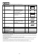
Cable type
Facility type All facility types
Type Shielded cable CVVS·CPEVS
No. of cores 2-core cable
Cable size Minimum 1.25 mm
2
Maximum transmission line distance between the outdoor unit
and the farthest indoor unit
200 m
Distance of the transmission line for the central control system
and indoor-outdoor transmission line to the farthest indoor unit
(Maximum line distance via outdoor unit)
500 m
* The maximum line distance from the power supply unit on
the transmission line for the central control system to each
outdoor unit or to the system controller is 200 m.
a
c
bde
f
g
10m
Centralized control transmission line Indoor-outdoor transmission line
Centralized
controller
(AG-150A)
Outdoor
unit
Outdoor
unit
Power supply
unit for
transmission line
Indoor unit Indoor unit
Indoor unit
Indoor unitIndoor unit
M-NET
remote
controller
WT05368X08.fm Page 7 Thursday, March 17, 2011 9:21 AM