
Installation manual

- 8 -
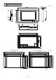
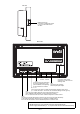
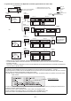
2. System with connection to an Expansion controller (system with 51 or more units)
• Refer to the PAC-YG50ECA Expansion controller Installation/Instructions Manual for how to set the IP address.
• The same M-NET address cannot be used twice in the same M-NET system that connects to the same PAC-YG50ECA
Expansion controller.
See section 1 “Standard configuration” for how to set the addresses for the equipments that are connected to the Expansion
controller within an M-NET system.
NOTES
* The DB No. of PAC-YG50ECA is found on the package box and the controller itself in the [DB No. : **] format.
Only the Expansion controllers with the same DB No. as the AG-150A can be connected to the AG-150A. Be sure to check the
DB No. before connecting the Expansion controller to the system.
If the DB numbers of the AG-150A and PAC-YG50ECA do not match, the software needs to be updated. Consult your dealer.
* Provide “one-point grounding” for the M-NET transmission line (centralized control system) by grounding the shield of the an
Expansion controller. (Class-D grounding)
Ground the indoor-outdoor transmission line in each outdoor unit refrigerant system.
* Set the centralized control switch (SW2-1) on the outdoor units on the M-NET line to ON.
(Refer to the outdoor unit Installation Manual for the details of the dipswitch settings.)
TB7 TB3
ME
R2
TB7 TB3
ME ME
000
051
TB7 TB3
ME ME
TB7 TB3
ME ME
001
101 103
101 103
101 103
106
002
006 007 008 009 010
003 004 005
001 002 003 004 005
001 002 003 004 005
056
057
051
051
000
000
Power supply (DC24V)
Centralized controller
Model name: AG-150A *
1
192.168.1.1
Power supply unit (sold separately)
Model name: PAC-SC51KUA *
2
*1: M-NET terminals will not be used.
*2: Terminal block TB2 will not be used.
M-NET
Outdoor unit
Expansion controller
Model name:
PAC-YG50ECA
192.168.1.211
Expansion controller
Model name:
PAC-YG50ECA
192.168.1.212
Expansion controller
Model name:
PAC-YG50ECA
192.168.1.213
M-NET
Outdoor unit
M-NET
Outdoor unit
M-NET
Outdoor unit
Group 1-1 Group 1-2
Indoor unit
Local remote
controller
LAN
M-NET
transmission line
Figures in indicate IP address.
Figures in indicate M-NET address.
Group 1-3
Group 2-1 Group 2-2
Group 3-1 Group 3-2
BC controller
LOSSNAY
unit
LOSSNAY
unit
LOSSNAY
unit
LAN
Switching
HUB
LAN
LAN
M-NET
M-NET
M-NET
• This diagram only
shows transmission
line configurations.
Power wires are
omitted.
DB No. appears here.
Label contents
WT05368X08.fm Page 8 Thursday, March 17, 2011 9:21 AM