
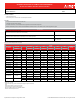
Electric Heat Kit Submittal

Job Name:
System Reference: Date:
Specications are subject to change without notice.
© 2021 Mitsubishi Electric Trane HVAC US LLC. All rights reserved.
OPTIONAL ELECTRIC HEAT KIT FOR MULTI-POSITION AIR HANDLER
USE WITH: PVFY-P-NAMU-E/E1; MVZ-A-AA4/7; SVZ-KP-NA; PVA-A-AA4/7
GENERAL FEATURES:
• 208/240V Electric Heat Kits
• Mounts directly to the air outlet connection of the Multi-position Air Handler
ACCESSORIES
Separate Power Kit for MVZ and PVA models
This kit allows the installer to connect power from a source other than the outdoor unit to the air handler.
(S2 & S3 still must connect from outdoor unit for communication)
SPTB1
Auxiliary Heat Lockout for MVZ, SVZ and PVA models
This option prevents the electric heat kit from operating above a set outside temperature.
ETC-211000-MIT
Replacement Temp Probe for ETC-211000-MIT
1309007-044
(See note on best design practice on page 3)
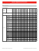
ELECTRICAL SPECIFICATIONS
Electric Heat
Part Number
Heater kW Heater Amps
1
MCA
1
MOP
1
Htr & Mtr
Amps2
MCA
2
MOP
2
Factory
Installed Circuit
Breaker
208V/240V 208V/240V 208V/240V 208V/240V 208V/240V 208V/240V 208V/240V
EH03-SVZ-S 2.3/3.0 10.8/12.5 13.5/15.6 15/20 13.2/14.9 16.5/18.6 20/20 20
EH05-SVZ-S 3.8/5.0 18.1/20.8 22.6/26 25/30 20.5/23.2 25.6/29 30/30 30
EH08-SVZ-S 6.0/8.0 28.9/33.3 36.1/41.7 40/45 31.3/35.7 39.1/44.7 40/45 45
EH05-SVZ-M 3.8/5.0 18.1/20.8 22.6/26 25/30 21.4/24.1 26.7/30.2 30/30 30
EH08-SVZ-M 6.0/8.0 28.9/33.3 36.1/41.7 40/45 32.2/36.6 40.2/45.8 45/50 50
EH10-SVZ-M 7.5/10 36.1/41.7 45.1/52.1 50/60 39.4/45 49.3/56.2 50/60 60
EH03-MPA-S(B) 2.3/3.0 10.8/12.5 13.5/15.6 15/20 13.2/14.9 16.5/18.6 20/20 20
EH05-MPA-S(B) 3.8/5.0 18.1/20.8 22.6/26 25/30 20.5/23.2 25.6/29 30/30 30
EH08-MPA-S(B) 6.0/8.0 28.9/33.3 36.1/41.7 40/45 31.3/35.7 39.1/44.7 40/45 45
EH03-MPA-M(B) 2.3/3.0 10.8/12.5 13.5/15.6 15/20 14.1/15.8 17.7/19.8 20/20 20
EH05-MPA-M(B) 3.8/5.0 18.1/20.8 22.6/26 25/30 21.4/24.1 26.7/30.2 30/30 30
EH08-MPA-M(B) 6.0/8.0 28.9/33.3 36.1/41.7 40/45 32.2/36.6 40.2/45.8 45/50 50
EH10-MPA-M(B) 7.5/10 36.1/41.7 45.1/52.1 50/60 39.4/45 49.3/56.2 50/60 60
EH10-MPA-L(B) 7.5/10 36.1/41.7 45.1/52.1 50/60 40.6/46.2 50.8/57.7 60/60 60
EH15-MPAS-L(B) 11.3/15
Circuit 1 27.1/31.2 33.9/39.1 35/40 31.6/35.8 39.5/44.7 40/45 45
Circuit 2 27.1/31.2 33.9/39.1 35/40 27.1/31.2 33.9/39.1 35/40 40
EH17-MPAS-L(B) 13.2/17.5
Circuit 1 31.6/36.5 39.5/45.6 40/50 36.1/41 45.1/51.2 45/60 60
Circuit 2 31.6/36.5 39.5/45.6 40/50 31.6/36.5 39.5/45.6 40/50 50
1
Heater amps; no motor
2
Heater and motor amps (connect air handler power supply to largest circuit breaker)
60Hz
Motor amps are placed on circuit 1 when required
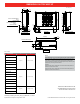
Unit tested at 0.60 in WG external static pressure
Minimum installation clearance to combustible material 0”
Maximum outlet air temperature 200° F
CAUTION:
• Do not power the Electric Heat Kit from the outdoor unit.
• A separate power supply must be provided.
• Air handler must be set on non-combustible oor when using electric heat in the downow conguration.
• Maximum external static pressure of 0.60 in WG for all installations with electric heaters. For more details, see note on best design practice on page 3.
□
□
□