Floor and Ceiling Type Air-Conditioner MCFH-A24WV CONTENTS 1. THE FOLLOWING SHOULD ALWAYS BE OBSERVED FOR SAFETY ........................................................................................... 2 [FLARE CONNECTION TYPE] HFC utilized R410A INSTALLATION MANUAL 2. SELECTING THE INSTALLATION LOCATION ............................... 2 3. INSTALLATION DIAGRAM & ACCESSORIES ................................ 3 4. INDOOR UNIT INSTALLATION ....................................................... 4 5.
1. THE FOLLOWING SHOULD ALWAYS BE OBSERVED FOR SAFETY 2. SELECTING THE INSTALLATION LOCATION • Please provide an exclusive circuit for the air conditioner and do not connect other electrical appliances to it. Please report to your supply authority or obtain their consent before connecting this equipment to the power supply system. • Be sure to read “THE FOLLOWING SHOULD ALWAYS BE OBSERVED FOR SAFETY” before installing the air conditioner.
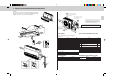
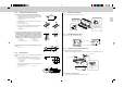
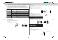
. INSTALLATION DIAGRAM & ACCESSORIES Remark: Accessories of this unit are packed inside the unit. Please remove the front grille as shown in the right (See “FRONT GRILL REMOVAL”), and check accessories before installation.
. INDOOR UNIT INSTALLATION FLARED CONNECTIONS 4-1 • This unit has flared connections on both indoor and outdoor sides. • Refrigerant pipes are used to connect the indoor and outdoor units as shown in the figure below. • Insulate both refrigerant and drain piping completely to prevent condensation. 4-1-(1) a 25 m max. 10 m max. 10 max. 7 m maximum Exceeding 7 m No additional charge required Additional charge required Details are printed on pattern.
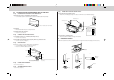
4-1-(2) FIXING OF INSTALLATION PLATES 1 1028 mm Remove 3 screws Installation plate 1 • Be sure to confirm letters “FRONT” in installation plates 1, set “FRONT” side to air outlet side of indoor unit. (Fig. 1) (Fig. 2) J K-1 K-2 (Fig. 3) Knockout hole for drain pipe 4-1-(6) 0 Unit fixing screw 2 b 1 5 Ø7 115 Hole for refrigerant pipe 40 b Unit fixing screw 2 a Ø c • Specially, drill the hole for drain pipe with designate dimension to keep an inclination.
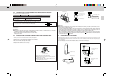
4-2 4-2-(1) A CASE OF INSTALLATING INDOOR UNIT ON THE WALL 4-2-(6) FIXING UNIT TO INSTALLATION PLATES 1. Suspending unit from installation plate. • Hoist unit so that hanging bolt (4) on the sides of unit fit into holes in installation plate 1. MOUNTING INSTALLATION PLATE FIXING BOLTS 1. Determine the locations of installation plate fixing bolts. • Use installation pattern to determine the locations of installation plate fixing bolts J.
4-4 Terminal cover POWER SUPPLY AND CONNECTING WIRE SPECIFICATIONS 3 N Use special room air conditioning circuit. Rated voltage 230 V Breaker capacity 10 A Indoor and Outdoor connecting wire Specification Indoor/outdoor unit connecting wire B 2-core 1.0 mm2 Power supply cord 3-core 1.0 mm2 or more, in conformity with Design 245 IEC 57 Power supply cord H Screw Three core with ground IEC cord 2 Cable 2-core 1.0 mm , in conformity with Design 245 IEC 57.
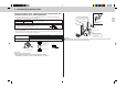
2. In case of connecting drain pipe D to drain-joint bush through drain hose. • Drain hose 7 which is contained in accessories is flexible, so use it when drain pipe D should be alternated direction. • Be sure to wind pipe cover which is provided in accessories around drain hose with vinyl tape. • Cut VP-20 in dimension as shown at the right, and connect drain-joint bush with drain hose with adhesive. 2. In case that pipes jut out from bottom surface of the indoor unit. (Fig.
5. OUTDOOR UNIT INSTALLATION INDOOR/OUTDOOR UNIT CONNECTING WIRE CONNECTION AND OUTDOOR POWER SUPPLY CORD CONNECTION • Connect the indoor/outdoor unit connecting wire B from the indoor unit correctly on the terminal block. • For future servicing, give extra length to connecting wire. Rated Voltage Breaker capacity 230 V 25 A Be sure to fix the indoor/outdoor unit connecting wire B and power supply cord H using this cord clamp.
6. INDOOR/OUTDOOR UNIT CONNECTION FINISHING AND TEST RUN 6-1 Tools dedicated for the air conditioner with R410A refrigerant 2. Burrs removal • Completely remove all burrs from the cut cross section of pipe. • Put the end of the copper pipe to downward direction as you remove burrs in order to avoid to let burrs drop in the piping. The following tools are required for R410A refrigerant. Some R22 tools can be substituted for R410A tools.
6-3 PIPE CONNECTION 6-4 1. Indoor unit connection • Connect both liquid and gas piping to the indoor unit. - Apply a thin coat of refrigerant oil on the seat surface of pipe. - For connection first align the center, then hand tighten the first 3 to 4 turns of flare nut. - Use tightening torque table below as a guideline for the indoor unit side union joint section, and tighten using two wrenches. Excess tightening damages the flared section. Pipe diameter mm 6.35 15.
6-5 TEST RUN 6-6 • Before performing the test run, recheck for any wrong wiring. Wrong wiring prevents normal operation or results in blown fuse disabling operation. When the indoor unit is controlled with the remote controller, the operation mode, set temperature, and the fan speed are memorized by the indoor electronic control P.C. board. The auto restart function sets to work the moment the power has restored after power failure, then, the unit will restart automatically.
7. FOR MOVEMENT AND MAINTENANCE 7-1 FRONT PANEL REMOVAL 1. Remove front grill. • Remove 3 screws. (See to 4-1-(4)) (Page 5). Lock 2. Remove front panel. • Remove 10 screws as shown in the right. • Unlock front panel by pulling it toward yourself (1) and then pull it down as the arrow (2). • After removing the front panel, it is possible to service many parts. 2 Front panel 1 7-2 GAS CHARGE 1. Connect gas cylinder to the service port of stop valve (3-way). 2.
This product is designed and intended for use in the residential, commercial and light-industrial environment.