
Installation manual


11
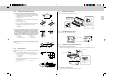
6-3 PIPE CONNECTION
1. Indoor unit connection
• Connect both liquid and gas piping to the indoor unit.
- Apply a thin coat of refrigerant oil on the seat surface
of pipe.
- For connection first align the center, then hand tighten
the first 3 to 4 turns of flare nut.
- Use tightening torque table below as a guideline for
the indoor unit side union joint section, and tighten us-
ing two wrenches. Excess tightening damages the
flared section.
Pipe diameter Tightening torque
mm N·m kgf·cm
6.35 13.7 to 17.7 140 to 180
15.88 73.5 to 78.4 750 to 800
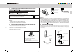
2. Outdoor unit connection
• Connect pipes to stop valve pipe joint of the outdoor unit in
the same manner applied for the indoor unit.
- For tightening, use a torque wrench or spanner, and
use the same tightening torque applied for the indoor
unit.
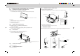
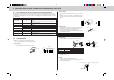
3. Refrigerant pipe insulation
• Use pipe cover (foam polyethylene 8 mm thickness) which
is contained in accessories, insulate both liquid and gas
pipes together. Put the refrigerant piping and apply piping
tape C.
a Indoor unit refrigerant pipe
b Flare joint
d Pipe cover
A Refrigerant pipe
C Piping tape
4. Knockout cover
• Attach knockout cover 9 to close knockout hole to prevent
rat or something strange from getting into the indoor unit.
9 Knockout cover
0 Screw for 9 4 × 10 mm
A
b
a
c
d
c
9
0
Connecting wire and
refrigerant pipes
must be separated.
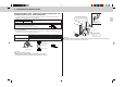
6-4 PURGING PROCEDURES · LEAK TEST
• Use the vacuum pump for air purging for the purpose of environmental protection.
PURGING PROCEDURES
Connect the refrigerant pipes (both liquid pipe and the gas pipe) between the indoor and the outdoor unit.
Remove the service port cap of the stop valve on the side of the outdoor unit gas pipe. (The stop valve will
not work in it initial state fresh out of the factory (totally closed with cap on).)
Connect the gauge manifold valve and the vacuum pump to the service port of the stop valve on the gas
pipe side of the outdoor unit.
Run the vacuum pump. (Vacuumize for more than 15 minutes.)
Check the vacuum with the gauge manifold valve, then close the gauge manifold valve, and stop the vacuum
pump.
Leave as it is for one or two minutes. Make sure the pointer gauge manifold valve remains in the same
position. Confirm that the pressure gauge shows–0.101 Mpa [Gauge] (–760 mmHg).
Remove the gauge manifold valve quickly from the service port of the stop valve.
After refrigerant pipes are connected and evacuated, fully open all stop valves on both sides of gas pipe and
liquid pipe.
Operating without fully opening lowers the performance and this causes trouble.
Pipe length up to 7 m
No gas charge is needed.
Pipe length exceeding 7 m
Charge the prescribed amount of
gas. (refer to 3)
Tighten the cap to the service port to obtain the initial status.
Retighten the cap.
Leak test
Tightening torque
N·mkgf·cm
Cap for service port 13.7 to 17.7 140 to 180
Cap for stop valve 19.6 to 29.4 200 to 300
*Close
*Open
Hexagonal wrench
Stop valve
*4 to 5 turns
Stop valve
(or the vacuum pump with
the function to prevent the
back flow)
Gauge manifold
valve (for R410A)
Pressure gauge
(for R410A)
Compound pressure
gauge (for R410A)
-0.101MPa
(-760 mmHg)
Handle
Low
Handle High
Window
Charge hose
(for R410A)
Vacuum
pump
Adapter for preventing the
back flow
Charge hose
(for R410A)
Service port
Stop
valve