
Installation manual


4
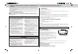
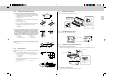
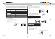
FLARED CONNECTIONS
• This unit has flared connections on both indoor and outdoor sides.
• Refrigerant pipes are used to connect the indoor and outdoor units as shown in the figure below.
• Insulate both refrigerant and drain piping completely to prevent condensation.
Limits
Pipe length 25 m max.
Height difference 10 m max.
No. of bends 10 max.
• Refrigerant adjustment … If pipe length exceeds 7 m, additional refrigerant (R410A) charge is required.
(The outdoor unit is charged with refrigerant for 7 m pipe length.)
Pipe length
7 m maximum No additional charge required —
Exceeding 7 m Additional charge required Refrigerant to be added 20 g/m
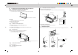
PIPING PREPARATION
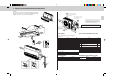
1 Table below shows the specifications of pipes commercially available.
Pipe Outside diameter Insulation thickness Insulation material
For liquid 6.35 mm 8 mm Heat resisting foam plastic
For gas 15.88 mm 8 mm 0.045 specific gravity
• Use a copper pipe or a copper-alloy seamless pipe with a thickness of 0.8 mm (for ø6.35) or 1.0 mm (for
ø15.88). Never use any pipe with a thickness less than 0.8 mm (for ø6.35) or 1.0 mm (for ø15.88), as the
pressure resistance is insufficient.
2 Ensure that the 2 refrigerant pipes are well insulated to prevent condensation.
3 Refrigerant pipe bending radius must be 100 mm or more.
Caution:
Be sure to use the insulation of specified thickness. Excessive thickness may cause incorrect installa-
tion of the indoor unit and lack of thickness may cause dew drippage.
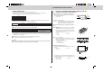
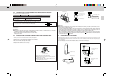
4-1 A CASE OF SUSPENDING INDOOR UNIT FROM THE CEILING
4-1-(1) MOUNTING INSTALLATION PLATE FIXING BOLTS
4. INDOOR UNIT INSTALLATION
1. Determine the locations of installation plate fixing bolts.
• Use installation pattern to determine the locations of instal-
lation plate fixing bolts J.
a Installation pattern
Details are printed on pattern.
Attention: Surrounding temperature and humidity conditions
may cause paper pattern to shrink or expand.
(Measure dimensions before drilling holes.)
2. Suspension structure (Give site of suspension strong struc-
ture).
■ Wood structure
• Select tie beam (one-story houses) or second-floor
girder (two story houses) as reinforcement member.
• Use sturdy beams of at least 60 mm square for beam
pitch of 900 mm or less or of at least 90 mm square for
beam pitch of 900-1800 mm.
a Pitch b Ceiling
c Rafter d Bracket
e Roof beam
■ Ferroconcrete Structures
• Secure installation plate fixing bolts J as shown at the
right or use angle-stock bracework to install installa-
tion plate fixing bolts J.
f Use inserts rated at 100-150 kg each
g Steel reinforcing rod
J Installation plate fixing bolts
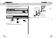
3. Installation plate fixing bolts pitch.
• Use the installation plate fixing bolts J M10 (× 4 procure
locally).
a Indoor unit b Air outlet
1 Installation plate
• Projecting dimension of installation fixing bolts J from hori-
zontal base line against which you fix installation plate 1
as within at the right.
c Horizontal base line 1 Installation plate
J Installation fixing bolts
a
*Remove installation pattern after installation.
b
c
d
e
a
a
b
a
1
300 mm
150 mm
1065 mm
f
J
g
c
J
1
max. 40 mm