
Installation manual


5
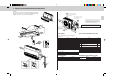
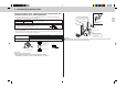
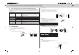
4-1-(4) FRONT GRILLE REMOVAL
• Remove front grille and transportation support.
4-1-(5) OPENING KNOCKOUT HOLE
• Remove knockout holes with hammering it.
4-1-(6) FIXING UNIT TO INSTALLATION PLATES
1. Suspending unit from installation plates.
• Hoist unit so that hanging bolt (4) on the sides of unit fit into holes in installation plates 1.
2. Securing unit to installation plates.
• Be sure to tighten unit fixing screw 2 to unit securely.
FRONT
Remove 3 screws
Transportation support
* After installing com-
pletely, please remove
this part because this is
used for transportation
only.
Front grille
Knockout hole
Knockout hole for drain pipe
Unit fixing screw 2
Unit fixing screw 2
Hanging bolt
• Be sure to set hanging bolt
in this position to keep
unit’s inclination.
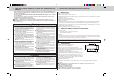
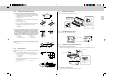
4-1-(2) FIXING OF INSTALLATION PLATES
1. Set installation plates to installation plate fixing bolts.
• Set installation plates 1 to installation plate fixing bolts J
so that the distance between insides of installation plates
is adjusted to length as shown in the right.
1 Installation plate
• Installation plates 1 should be fixed on one way direction,
as shown in Fig. 1.
Don’t fix as shown in Fig. 2.
• Be sure to confirm letters “FRONT” in installation plates 1,
set “FRONT” side to air outlet side of indoor unit.
a “FRONT”
1 Installation plate
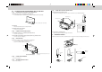
2. In case of fixing installation plates 1 above the ceiling, put
installation plates fixing bolt through a nut, a spring washer,
the installation plate, a spring washer, and double nut. (Fig. 3)
In case of fixing installation plates 1 forward the ceiling
directly, also put installation plate fixing bolt through the in-
stallation plate, a spring washer, and double nuts. (Fig. 4)
a Ceiling K-1 Nut (M10)
1 Installation plate K-2 Spring washer
J Installation plate fixing bolt K-3 Double nut (M10)
3. Check that the four corners are horizontal with level gauge.
(Fig. 5)
a Level gauge
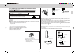
4-1-(3) DRILLING HOLE
Determine the locations of holes for refrigerant pipe A and drain
pipe D.
• Use the installation pattern as mentioned in 4-1-(1).
• Be sure to confirm the dimensions as shown in the right.
a Horizontal base line b Hole for refrigerant pipe
c Hole for drain pipe
1 Installation plate
• Specially, drill the hole for drain pipe with designate dimen-
sion to keep an inclination.
d Horizontal base line e Hanging bolt
f Wall
1
1028 mm
1
a
J
a
K-1
K-2
1
K-2
K-3
1
K-2
K-3
J
a
(Fig. 1) (Fig. 2)
(Fig. 3) (Fig. 4)
a
1
b
c
0
115
188
132
124
0
Ø40
Ø75
a
(Fig. 5)
(unit : mm)
(unit : mm)
e
f
d
188
193
199
204
115
155
0
100
200
300
FRONT