
Installation manual


7
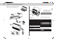
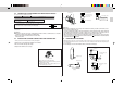
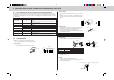
1 Use care not to make mis-wiring.
2 Firmly tighten the terminal screws to prevent
them from loosening.
3 After tightening, pull the wires lightly to con-
firm that they do not move.
Loosen terminal screw
Terminal block
Connection details
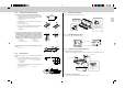
4-4 POWER SUPPLY AND CONNECTING WIRE SPECIFICATIONS
Use special room air conditioning circuit.
Rated voltage Breaker capacity Power supply cord
230 V 10 A 3-core 1.0 mm
2
or more, in conformity with Design 245 IEC 57
Indoor and Outdoor connecting Cable 2-core 1.0 mm
2
, in conformity with
wire Specification Design 245 IEC 57.
• Peel off both ends of connecting wire and power supply cord as
shown in the right.
• Be careful not to contact connecting wire with piping.
Connect to the plug, or to a power switch which has a gap of 3 mm or more when open to interrupt the source
power phase.
Warning:
• A means for disconnection of the supply with an isolation switch, or similar device, in all active
conductors shall be incorporated in the fixed wiring.
• Never cut the power cord and connect it to other wires.
It may cause a fire.
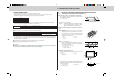
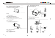
4-5 INDOOR AND OUTDOOR CONNECTING WIRE CONNECTION
• Wiring connections should be made following the diagram.
1. Remove two screws and pull the terminal cover forward.
2. Be sure to fix the cable by cable clamp.
3. Replace the terminal cover securely.
Cable clamp
Screw
Terminal cover
Warning:
• Attach the electrical part cover securely. If it is attached incorrectly, it could result in a fire, an elec-
tric shock due to dust, water, etc.
• Use the specified indoor/outdoor unit connecting wire to connect the indoor and outdoor units and
fix the wire to the terminal block securely so that no stress is applied to the connecting section of
the terminal block. Incomplete connection or fixing of the wire could result in a fire.
• When connecting the power supply cord to the power supply source, be sure to connect each wire
to the correct pole. Be sure to connect the Live wire side to the
L
terminal and connect the Neutral
conductor side to the
N
terminal.
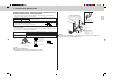
4-6 REFRIGERANT PIPE WORK
• Refrigerant pipes which are connected at side of indoor unit must be processed as below, and processed
figure will be differently made means of which the indoor unit is installed or which direction refrigerant pipes
are connected in.
1. In case that pipes are cut out from back surface of the indoor unit. (Fig. 1)
Process figure
(Fig. 1)
90°
R25 (R1"
) − R75 (R3"
)
110
90°
R15 − R50 (R2"
)
70
Refrigerant pipe
Refrigerant pipe
Flare nut
Flare nut
Refrigerant pipe (gas)
OD ø15.88
Refrigerant pipe (liquid)
OD ø9.52
Three core with
ground IEC cord
Power supply cord H
65 mm
15 mm
Indoor terminal block
Outdoor terminal block
3 N
3
N
Indoor/outdoor unit
connecting wire B
2-core 1.0 mm
2
L
~
N
~