
Installation manual


6
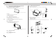
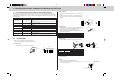
1028 mm
1065 mm
80 mm
95 mm
132 mm
300 mm
300 mm
155 mm
Ø75
Ø75
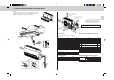
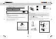
4-2 A CASE OF INSTALLATING INDOOR UNIT ON THE WALL
4-2-(1) MOUNTING INSTALLATION PLATE FIXING BOLTS
1. Determine the locations of installation plate fixing bolts.
• Use installation pattern to determine the locations of installation plate fixing bolts J.
2. Sturdy wall
• Find structural material (such as stud) in the wall.
3. Installation plate fixing bolt pitch.
• See to 4-1-(1) 3. (Page 5)
4-2-(2) FIXING OF INSTALLATION PLATES
1. Set installation plates 1 to installation plate fixing bolts J.
• See to 4-1-(2) 1. (Page 5)
2. Put installation plate fixing bolt through spring washer (2), and double nuts.
• See to 4-1-(2) 2 Fig. 4. (Page 5)
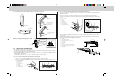
4-2-(3) DRILLING HOLE
Determine the location of hole for refrigerant pipes and drain pipe.
• Use the installation pattern as mentioned in 4-2-(1).
• Be sure to confirm the dimensions as below.
4-2-(4) FRONT GRILLE REMOVAL
• See to 4-1-(4). (Page 5)
4-2-(5) OPENING KNOCKOUT HOLE
• See to 4-1-(5). (Page 5)
Installation pattern
* Remove installation pattern after installing.
Horizontal base line
Hole for refrigerant and drain pipe
(in the case of downward piping)
Hole for refrigerant and drain pipe (in the case of
rear piping)
Installation plate 1
FRONT
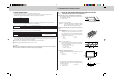
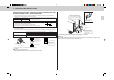
4-2-(6) FIXING UNIT TO INSTALLATION PLATES
1. Suspending unit from installation plate.
• Hoist unit so that hanging bolt (4) on the sides of unit fit into holes in installation plate 1.
2. Securing unit to installation plates.
• Be sure to tighten unit fixing screw 2 to unit securely.
4-3 KNOCKOUT COVER
• After removing the knockout holes, attach knockout cover 9 on the knockout hold edge (shown as below).
Unit fixing screw 2
Installation plate 1
Hanging bolt
Hanging bolt
Unit fixing screw 2
• Be sure to set
hanging bolt in
this position.
Knockout
cover 9
Refrigerant
pipe
Drain pipe
Knockout
Knockout
Refrigerant
pipe
Drain pipe
Knockout
A CB
Refrigerant
pipe
Drain pipe