
Installation manual


9
5. OUTDOOR UNIT INSTALLATION
INDOOR/OUTDOOR UNIT CONNECTING WIRE CONNECTION AND
OUTDOOR POWER SUPPLY CORD CONNECTION
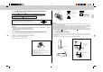
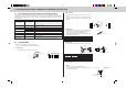
• Connect the indoor/outdoor unit connecting wire B from the indoor unit correctly on the terminal block.
• For future servicing, give extra length to connecting wire.
Connect to the supply terminals and leave a contact separation of at least 3 mm
at each pole to disconnect the source power pole. (When the power switch is shut
off, it must disconnect all poles.)
Rated Voltage Breaker capacity
230 V 20 A
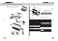
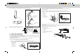
• Peel off both ends of connecting wire (extension wire). When too
long, or connected by cutting off the middle, peel off power sup-
ply wire to the size as shown in the right.
• Be careful not to contact connecting wire with piping.
• Make earth wire a little longer than the others. (more than 35 mm)
• For the power supply cord and the indoor/outdoor unit connecting wires, be sure to use the ones in compli-
ance with the standards.
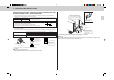
• Be sure to push the core until it is hidden and pull each cable to make sure that it is not pulled up incomplete
10 m or less
15 m or less
25 m or less
Power supply cord Specification
Indoor and Outdoor connecting wire
Specification
3-core 2.5 mm
2
or more, in conformity with Design 245 IEC 57.
3-core 4.0 mm
2
or more, in conformity with Design 245 IEC 57.
3-core 6.0 mm
2
or more, in conformity with Design 245 IEC 57.
Cable 2-core 1.0 mm
2
, in conformity with Design 245 IEC 57.
Loosen terminal screw.
Terminal block
Lead wire
<Connection details>
insertion may cause a risk of burning the terminal blocks.
Caution:
• Use care not to make mis-wiring.
• Firmly tighten the terminal screws to prevent them from loosening.
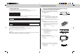
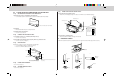
Service panel
Fixing screws
• After tightening, pull the wires lightly to confirm that they do not move.
Warning:
Be sure to attach the service panel of the outdoor unit securely. If it is not attached correctly, it could
result in a fire or an electric shock due to dust, water, etc.
Indoor terminal block
Outdoor terminal block
3 N
3
N
Indoor/outdoor unit
connecting wire B
2-core 1.0 mm
2
Be sure to put the left por-
tion into the square hole of
the service panel.
Be sure to fix the indoor/outdoor
unit connecting wire B and power
supply cord H using this cord
clamp.
Remove two fixing
screws to open the
service panel.
Valve cover
35 mm
15 mm
Three core with
ground IEC cord
Power supply cord H
N
~
L
~