
Installation Sheet

7
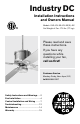
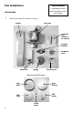
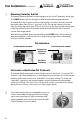
Identify control components from control package(s). In addition to a receiving
unit, your fan may have been ordered with a wall control (transmitter), a handheld
remote control (transmitter) or both.
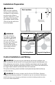
Insert receiving unit into hanging bracket
(between bracket arms) and make wire
connections according to wire colors, labels and
diagram below. If ordered, install wall switch into
wall box, taking note of dip-switch settings and
related instructions referenced below.
6
receiving unit receiving unit
switch
plate
wall
switch
hardware &
wire nuts
batteries
handset
wall clip &
hardware
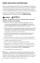
WARNING
See Pages 2-3
POWER OFF
Circuit Breaker
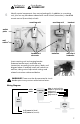
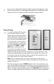
WARNING!! Power must be disconnected at circuit
breaker prior to any contact with electrical wires.
Wiring Diagram
red motor 1
blue for optional light
white for optional light
antenna
purple motor 2
white
black
gray motor 3
receiving
unit
A/C power in (neutral)
A/C power in (load)
wall
switch
fan or
fan and
light