
Installation Sheet

8
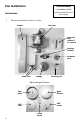
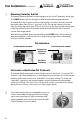
Fan Installation (continued)
Once wire connections are completed, remove set
screws on outside of hanging bracket, lift canopy
up to cover receiving unit, wire connections and
hanging bracket, then reinstall set screws on each
side of canopy to secure in place.
7
8
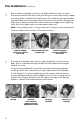
WARNING
See Pages 2-3
POWER OFF
Circuit Breaker
Dimming Selector Switch
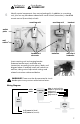
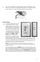
The remote handset and wall control ship pre-set for “on/off” operation of the light.
The LIGHT button will turn the light on and off when pressed and released.
To enable dimming function on the remote handset, move the vertically oriented
dip switch down from ON to 1 (or from X to D). On the wall control, move the
right (or lower) dip switch from ON to 2 (or from X to D). Dip switches are located
inside the battery cover of the remote handset and on the left side of the wall
control. See image below.
With dimming enabled, pressing and holding the LIGHT button will increase or
decrease brightness, with the minumum and maximum light levels indicated by
a “chirp” from the receiver.
Universal or Dedicated RF Channels
The remote handset and wall control ship pre-set to a “Universal” or common RF
channel. If you have multiple fans in close proximity, you will want to set the remote
handset and/or wall control to an “Individual” (or unique) channel. To select the
“Individual” channel on the remote handset, move the horizontally oriented dip
switch from ON to 1 (or from U to I). On the wall control, move the left (or upper)
dip switch from ON to 1 (or from U to I). See images above.
Inside remote handset
Dip Switches:
Left side of wall control
Universal or
Individual
Channel
On/Off or
Dimming
Top
Bottom