GAS-FIRED SEPARATED COMBUSTION UNIT HEATERS MODEL HDS MODEL HDC MODEL PTS / BTS 6-175.
TABLE OF CONTENTS Modine’s separated combustion unit heaters are designed for the heating requirements of commercial and industrial buildings with select models available for residential garage heating as well. The separated combustion units draw combustion air from outside to ensure that the unit will always have plenty of fresh, clean air for combustion, reducing common concerns about dusty, dirty, humid, or negative space pressure applications.
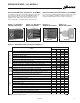
DESIGN FEATURES - ALL MODELS Separated Combustion Unit Heaters, 30-125MBH Separated Combustion Unit Heaters, 150-400MBH For residential, commercial or industrial applications that require a low profile unit, Modine offers the Hot Dawg®. Capable of being installed just one inch below the ceiling, the superior quality of the Hot Dawg makes it a preferred choice for a variety of applications, including garages and workshops.
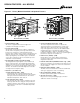
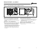
DESIGN FEATURES - ALL MODELS Figure 4.1 - Factory Mounted Standard and Optional Features 6 4 6 8 13 1 10 8 10 2 1 5 4 2 3 7 5 Models HDS/HDC (30-125MBH) M Power Exhauster (STD) All units are supplied with a round vent pipe and combustion air inlet pipe connections. N Pressure Switch (STD) An automatic reset vent pressure switch is supplied on all units and is designed to prevent operation of the main burner in the event there is restricted venting of flue products.
DESIGN FEATURES - ALL MODELS Figure 5.1 - Factory Mounted Standard and Optional Features (outlet) 1 1 18 (inlet) 17 19 11 20 Finger Proof Fan Guard (STD thru 125, OPT 150-400) Propeller units may be equipped with an optional finger proof fan guard for added protection. The finger proof fan guard is installed at the factory in place of the standard fan guard.
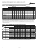
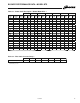
GENERAL PERFORMANCE DATA - MODELS HDS & PTS Table 6.
GENERAL PERFORMANCE DATA - MODELS HDC & BTS Table 7.
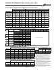
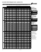
BLOWER PERFORMANCE DATA - MODEL HDC Table 8.1 - Power Code Description - HDC Models Power Code 01 Unit Voltage 115/60/1 HDC60 HDC75 HDC100 HDC125 1/4 HP 1/3 HP 1/2 HP 1/2 HP Blower Speed Curves Models (HDC 60-125) Low Medium High 684 60 741 55 808 50 889 45 988 40 1111 35 0.00 1270 0.10 0.20 0.30 0.40 0.50 0.60 65 1140 60 1235 55 1347 50 1481 45 1646 40 1852 35 0.00 0.70 2116 0.10 0.20 External Static Pressure (IN. WC) 0.50 0.60 0.70 0.
BLOWER PERFORMANCE DATA - MODEL BTS Table 9.
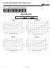
BLOWER PERFORMANCE DATA - MODEL BTS Table 10.1 - Blower Model BTS 150-250 (40-55°F temp rise for 250 size unit) M N O External Static Pressure (“W.C.) 0.0 Model Size ATR CFM 40 2778 45 2469 HP 1 1/2 1 55 2222 2020 150 60 1852 70 1709 1587 3241 45 2881 50 2593 60 65 2160 1994 418 175 - - 232 5.0 230 2.5 232 3.5 230 0.5 532 3.0 - - - - 229 2.0 4.5 175 - - 232 2.0 - - 612 582 692 175 1.5 - - 175 2.5 - - - - - - 4.
BLOWER PERFORMANCE DATA - MODEL BTS Table 11.1 - Blower Model BTS 250-400 (60-70°F temp rise for 250 size unit) M N O External Static Pressure ("W.C.) 0.0 Model Size ATR CFM HP 250 65 70 3086 2849 2646 1 1-1/2 360 5556 45 4938 50 4444 3704 40 6481 45 5761 5185 4321 490 241 3.0 - - 530 241 2.0 23 5.0 566 241 1.5 23 4.0 601 - 241 0.5 23 3.0 635 - 241 0.0 1 23 2.0 1-1/2 - - - 180 4.5 180 2.5 2 - - - - - - - 1/2 - - - - 241 4.5 241 3.
GAS CONTROL DATA - ALL MODELS Table 12.
ACCESSORIES - ALL MODELS Table 13.1 - Field Installed Accessories Model HD HDB PTS BTS Cabinet and Air Mover Feature Vertical Deflector Blades - Allows directional discharge air control in the left and right directions. Downward Air Deflector Hoods - Available in 30°, 60°, and 90° configurations these deflector hoods enable the unit to be mounted higher while still providing heat to the building occupants. Refer to page 14 for further details.
PERFORMANCE DATA - HOODS FOR PROPELLER MODELS Figure 14.1 - 30°, 60°, and 90° Downward Deflector Hoods Table 14.
PERFORMANCE DATA - HOODS FOR BLOWER MODELS Table 15.1 - Deflector Hood General Performance Data - Model HDC Model Airflow Size (cfm) 60 75 100 125 808 1010 1347 1543 Temp Rise (°F) 55 55 55 60 Mounting Blade Height Angle 30° Hood X Y Z 60° Hood X Y Z (ft) (ft) (ft) (ft) (ft) (ft) Table 15.
UNIT SELECTION Selection Procedure In order to properly select a unit heater it is necessary to have the following basic information. 1. Heating output capacity Model size output is to be matched against the heat loss to be replaced. 2. External static pressure (blower units only) The external static pressure (E.S.P.) is determined using the ASHRAE Guide for duct losses or provided by the design engineer. 3. Accessory internal static pressure (transitions, filters, etc.
UNIT SELECTION Selection Example (Blower Unit) Selection Example Conditions (Blower Unit) In the following example, select a unit heater to meet the following conditions: 1. Heating output capacity = 156,000 Btu/Hr per design engineer 2. External Static Pressure = 0.2. 3. Internal Static Pressure = 0.0. No static producing accessories are required at this point, but filters may be added later. 4. Heat exchanger and burner = Aluminized Steel 5. Gas Type = Propane 6. Gas Controls = Two Stage 7.
DIMENSIONAL DATA - HDS/HDC Figure 18.1 - Dimensional Drawings - Models HDS/HDC 13.5" BETWEEN 3/8"-16 MOUNTING HOLES (MODEL SIZES 100 AND 125 ONLY) 14.9" BETWEEN 3/8"-16 MOUNTING HOLES (MODEL SIZES 100 AND 125 ONLY) MOUNTING HOLES TYP 3/8" X 1" LONG G A ADJUSTABLE LOUVERS BLOWER (MODEL HDC ONLY) MOUNTING BRACKETS 10.0" 3.5" POWER VENTER VENT PIPE CONNECTION 1.
DIMENSIONAL DATA - MODEL PTS Figure 19.1 - Dimensional Drawings - Model PTS A G 4 MOUNTING HOLES R ADJUSTABLE LOUVERS U T POWER VENTER VENT PIPE CONNECTION S COMBUSTION AIR INLET ACCESS PANEL B GAS CONNECTION E OPENING L J K D OPENING I C H F T-STAT CONNECTION ELECTRICAL CONNECTION MOTOR CORD STRAIN RELIEF M (APPROX) Q (MIN DIST TO WALL) Table 19.1 - Dimensions (inches) - PTS M Models PTS150 PTS175 PTS200 PTS250 PTS300 PTS350 PTS400 A 35.53 42.53 42.53 42.53 42.53 42.53 42.
DIMENSIONAL DATA - MODEL BTS Figure 20.1 - Dimensional Drawings - Model BTS 6 MOUNTING HOLES G A BLOWER ENCLOSURE (OPTIONAL) 4 7/8" T FILTER RACK (OPTIONAL) 7/8" R ADJUSTABLE LOUVERS U W X V S POWER VENTER VENT PIPE CONNECTION COMBUSTION AIR INLET ACCESS PANEL B OxP E OPENING L F J GAS CONNECTION C K D OPENING N MOTOR CORD STRAIN RELIEF M (APPROX.) I T-STAT CONNECTION ELECTRICAL CONNECTION H Q (MIN DIST TO WALL) Table 20.
SPECIFICATIONS - ALL MODELS General A. Standards E.7.a. The solid state ignition system shall directly light the gas by means of a direct spark igniter each time the system is energized. All unit(s) shall include: A.1. ETL design certification for use in both the US and Canada to the ANSI Z83.8 - latest revision, standard for “Gas Unit Heater and Gas-Fired Duct Furnaces” for safe operation, construction, and performance. B. Mechanical Configuration B.2.
SPECIFICATIONS - ALL MODELS J.22. (opt) A 230V to 115V step down shall be provided for operation of the 115V unit (HDS/HDC/PTS models). J.23 (opt) A 460V to 115V step down shall be provided for operation of the 115V unit (HDS/HDC/PTS models). J.24. (opt) A 575V to 115V step down shall be provided for operation of the 115V unit (HDS/HDC/PTS models). G.5.e. The motor shall be provided with three speed taps to allow for adjustment of the blower rpm at the job site. (HDC model) J.25.
MODEL NOMENCLATURE Figure 23.1 - Model Number Designations PTS 200 A S 01 11 S B A N Factory Installed Option Digit N = None Separated Combustion Unit Configuration HDS - Propeller Unit, 30-125MBH HDC - Blower Unit, 60-125MBH PTS - Propeller Unit, 150-400MBH BTS - Blower Unit, 150-400MBH Future A = All MBH Input (refer to pages 6 & 7) 100 - 100,000 Btu/hr input 200 - 200,000 Btu/hr input 250 - 250,000 Btu/hr input etc.
The Modine brand has been the industry standard since Arthur B. Modine invented and patented the first lightweight, suspended hydronic unit heater in 1923. No other manufacturer can provide the combined application Products from Modine are designed to provide indoor air-comfort and ventilation solutions for residential, commercial, institutional and industrial applications.