
Product Brochure

6
6-175.7
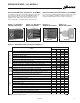
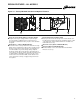
GENERAL PERFORMANCE DATA - MODELS HDS & PTS
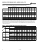
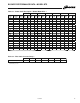
Table 6.1 - Propeller Unit Model HDS and PTS General Performance Data
P Amp draw data shown is operating amp draw at incoming power. For units that use a field installed accessory step-down transformer as noted, the amp draw shown is
the primary side operating amp draw. For sizing of circuit protection for equipment with transformers, please refer to the National Electric Code.
Supply
Voltage
Power Code
Model HDS Sizes Model PTS Sizes
30 45 60 75 100 125 150 175 200 250 300 350 400
01 (115V)
Motor Amps 2.40 2.40 1.95 1.95 2.50 2.20 2.50 2.50 4.60 4.60 7.00 7.00 8.80
Total Amps 3.75 3.75 3.3 3.3 5.05 4.75 5.05 5.05 7.15 7.15 8.11 8.65 10.45
Transformer kVA n/a n/a n/a n/a n/a n/a n/a n/a n/a n/a n/a n/a n/a
01 (115V) with
Transformer
Transformer kVA 0.50 0.50 0.50 0.50 1.00 1.00 1.00 1.00 1.00 1.00 1.00 1.00 1.50
208V Total Amps 2.05 2.05 1.80 1.80 2.79 2.63 2.79 2.79 4.20 3.95 4.48 4.78 5.78
01 (115V) with
Transformer
Transformer kVA 0.50 0.50 0.50 0.50 0.75 0.75 0.75 0.75 1.00 1.00 1.00 1.00 1.50
230V Total Amps 1.85 1.85 1.63 1.63 2.53 2.38 2.53 2.53 3.80 3.58 4.06 4.33 5.23
01 (115V) with
Transformer
Transformer kVA 0.50 0.50 0.50 0.50 0.75 0.75 0.75 0.75 1.00 1.00 1.00 1.00 1.50
460V Total Amps 0.93 0.93 0.81 0.81 1.26 1.19 1.26 1.26 1.90 1.79 2.03 2.16 2.61
01 (115V) with
Transformer
Transformer kVA 0.50 0.50 0.50 0.50 0.50 0.50 0.50 0.50 0.50 0.50 0.50 0.50 0.50
575V Total Amps 0.74 0.74 0.65 0.65 1.01 0.95 1.01 1.01 1.52 1.43 1.62 1.73 2.09
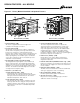
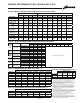
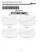
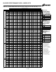
Table 6.2 - Propeller Unit Model HDS and PTS Operating Electrical Data P
Model HDS Sizes Model PTS Sizes
30 45 60 75 100 125 150 175 200 250 300 350 400
Btu/Hr Input M
30,000 45,000 60,000 75,000 100,000 125,000 150,000 175,000 200,000 250,000 300,000 350,000 400,000
Btu/Hr Ouput M
24,600 36,900 49,200 61,500 82,000 102,500 123,000 143,500 164,000 205,000 246,000 287,000 328,000
Entering Airflow (CFM)
@ 70°F
505 720 990 1160 1490 1980 2140 2725 2870 3995 4545 5280 5995
Outlet Velocity (FPM) 523 725 653 769 565 747 711 607 643 721 824 748 851
Air Temp. Rise (°F) 44 46 45 48 50 47 53 48 52 47 50 50 51
Max. Mounting
Height (Ft.) N
10 10 12 14 12 16 15 14 15 18 19 18 21
Heat Throw (Ft.) @
Max Mtg Ht N
25 27 36 38 42 56 51 50 53 62 69 65 74
Motor Type O
SP SP PSC PSC SP PSC PSC PSC PSC PSC PSC PSC PSC
Motor HP 1/15 1/15 1/12 1/12 1/12 1/8 1/6 1/6 1/3 1/3 1/2 1/2 3/4
Motor RPM 1550 1550 1625 1625 1050 1625 1075 1075 1075 1075 1075 1125 1125
115V
1 Phase
208V
1 Phase
230V
1 Phase
208V
3 Phase
230V
3 Phase
460V
3 Phase
575V
3 Phase
M Ratings shown are for elevations up to 2,000 ft. For elevations above 2,000 feet, ratings should be reduced at the rate of 4% for each 1,000 feet above sea level. (In
Canada see rating plate.) Reduction of ratings requires use of a high altitude kit.
N Data taken at 55°F air temperature rise. At 65°F ambient and unit fired at full-rated input. Mounting height as measured from bottom of unit, and without deflector
hoods.
O All motors used are produced, rated and tested by reputable manufacturers in accordance with NEMA standards and carry the standard warranty of both the motor
manufacturer and Modine. Motors on model sizes 100 and above are totally enclosed (Model size 75 and below are open drip proof) and all single phase motors have
built in thermal overload protection.