
Owner`s manual


INSTALLATION INSTRUCTIONS
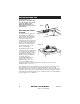
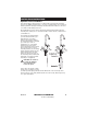
When determining the location of the bracket make sure you leave at least
1–1/2" of free space from the floor surface to the bottom of the filter (13) (or 15"
from floor to the underside filter connection of the Filter Life Indicator Module
(12)), and at least 4" of space on both sides to make the hose connections.
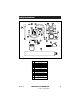
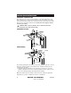
1. With the filter removed, use the Filter Life Indicator with Mounting Bracket
(12) as a template for marking the location of the mounting screws.
2. Connect one hose from the T-fitting to the Stop Valve on the Filter Life
Indicator Module. Connect the other hose from the Filter Life Indicator
Module outlet, up to the faucet. Make sure that all connections are at least
finger tight.
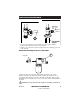
3. Attach the Filter Life Indicator with Mounting Bracket securely to the wall
using the self threading screws (supplied). If the cabinet wall is not solid
wood, locate the bracket so that the screws penetrate a wall stud to allow
adequate support for the weight of the filter unit.
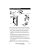
4. Using 2 wrenches, tighten all hoses securely to the Filter Life Indicator
Module. Use one wrench to hold the bracket firmly while using the second
wrench to tighten the hose nut. Attach filter to the Filter Mounting Bracket
(See “Filter Installation/Replacement” on page 10). Connect LED Wire to the Filter
Life Indicator Module.
CAUTION: Take care not to overtighten or crossthread the hose
connections on the plastic threads of the Filter Life Indicator Module.
13
LED Wire connection
9
HELPLINE: 1-877-DRINK-H2O
(1-877-374-6542)
INS412A
Stop valve