Da ta Char Data Chartt 1250 P aper less R ecor der Pa perless Recor ecorder Instr uction Man ual Instruction Manual 15 Columbia Drive, Amherst, NH 03031 Phone: 603-883-3390 Fax: 603-886-3300 Support email: support@monarchinstrument.
TABLE OF CONTENTS 1.0 INTRODUCTION 1.1 1.2 1.3 1.4 1.5 1.6 1.7 CHART SPEED TO SAMPLE SPEED REVIEWING DATA ZOOMING AND CONDITIONING DATA CUSTOMIZING TRIGGERING THE GRAPHICS LCD DISPLAY OTHER GRAPHIC MODES 2.0 INSTALLATION AND SETUP 2.1 2.2 2.3 2.4 2.5 2.6 UNPACKING 2.1.1 Initial Inspection 2.1.2 Unpacking Procedure 2.1.3 Detected Damage 2.1.4 Equipment Return 2.1.5 Storage INSTALLATION 2.2.1 Panel Mounting CONNECTION 2.3.1 Power Connections 2.3.2 Input Signal Connections 2.3.
.6 3.7 3.8 3.9 EVENT TRIGGERING STATUS LINE INDICATORS ENTERING VALUES TOP LEVEL MENU 4.0 ADVANCED SETUP 4.1 4.2 4.3 4.4 4.5 4.6 4.7 4.8 4.9 4.10 4.11 4.12 4.13 CHANNEL SETUP ALARMS RELAYS DISPLAY DATA CARD CLOCK BEEPER SAMPLE TRIGGER RECORD TRIGGER EXTERNAL INPUT ALT LANGUAGE UNIT TAG COMMS 5.0 MISCELLANEOUS 5.1 5.2 5.3 5.4 BATTERY BACKUP OPTION ETHERNET OPTION CALIBRATION 5.3.1 Basic Calibration 5.3.
WEEE NOTICE In order to comply with EU Directive 2002/96/EC on Waste Electrical and Electronic Equipment (WEEE): This product may contain material which could be hazardous to human health and the environment. DO NOT DISPOSE of this product as unsorted municipal waste. This product needs to be RECYCLED in accordance with local regulations, contact your local authorities for more information. This product may be returnable to your distributor for recycling - contact the distributor for details.
1.0 INTRODUCTION This instrument is a versatile Solid State Data Recorder / Panel Indicator. It has all the capability of a traditional paper recorder - variable chart speeds, the ability to review historic data, see trends and more, with a number of specific exceptions - NO PAPER to jam, no ink to smudge and no pens to clog or break. The data is stored in a Compact Flash memory card, which can be easily transported.
1.2 REVIEWING DATA One of the biggest features of this recorder is its ability to show historic data and trends. The data on the graphics screen can be rewound like a tape recorder, scrolling back in time, displaying past data on the screen while still recording data in real time. The data can also be compressed on screen, showing a whole day or week's worth of recording on one screen, enabling trends or irregularities to be spotted easily.
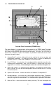
1.6 THE GRAPHICS LCD DISPLAY K L J M I N H X2 G F P E A B D C Recorder Front View showing TREND Display The above diagram is a representation of the recorder in the TREND mode. The alpha characters around the border point to various features of the unit and are described below. Not shown are the MENUS which pop up over the display. The menus are in the form of those shown in Sections 4 and 5. The numbers in parenthesis below refer to the section that covers the topic in detail.
selectable in 12 or 24 hour format. The user can also select European or American formats and auto daylight savings adjustment. See Clock setup. G Zoom Scale Indicator – shows the zoom scale for the channel indicated if > x1. Separate scale for each channel. See zooming. H The right hand edge of the graphics area in which the traces are displayed. This is the vertical scale area designated by the scale values at the top, center and bottom of the scale.
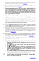
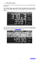
1.7 OTHER GRAPHIC MODES In addition to the full screen trend mode shown section 1.6, there are two additional graphic display modes. The Dual Digital mode, as shown below, enables both channels to be shown as Digital values similar to a digital panel meter. The user has the option of showing the displays in normal or reverse video (shown) modes, and the display can be set to blink on Alarm Condition.
2.0 INSTALLATION AND SETUP 2.1 UNPACKING 2.1.1 Initial Inspection Exercise care when unpacking the instrument from the shipping carton. The instrument is packed in a custom cardboard box to prevent damage during normal transit. If damage to the shipping carton is evident, ask the carrier’s representative to be present when the instrument is unpacked. 2.1.2 Unpacking Procedure To unpack your Recorder, first remove the cardboard retainer and instrument from the shipping carton.
NOTE: In order to fully comply with the CE EMC Directive 89/336/EEC, connections to the recorder should not exceed 3m (9.8ft) without adding additional filtering. The Recorder fits in a standard ¼ DIN panel cutout of 92 x 92 mm (3.62 x 3.62 in.) and requires 140mm (7.5 inches) panel depth not including space for power and input source cable. The thickness of the panel is immaterial, but panels thicker than .125 inch will require that the locking bars be cut down.
2.2.1.8 Using the screwdriver, tighten both screws so that the Recorder is held firmly in place. Do not over tighten, to avoid stripping the threads. DC Power Connector Relay Outputs Digital Input Locking Bar (2) Analog Inputs Retaining Screw (2) Temperature Compensator Figure 2.2 Rear View - Installation 2.3 CONNECTION 2.3.1 Power Connections WARNING NOTE: The Recorder is designed to be panel mounted and power should be considered to be permanently connected.
Before connecting any power or inputs to the unit, ensure that all signal wires and power cables are at zero voltage. The DC power is applied to the unit via a three-way screw terminal connector. The power supply is supplied with two tinned leads; the positive lead is identified by the RED shroud over the wire. The third connection is for system GROUND. You will require a small flat-head screwdriver. Connect the power and signal wires accordingly, noting carefully all polarities.
signal marked IN+, and a low or common signal marked IN-. The terminal marked Vo is the Auxiliary voltage output used to drive external sensors at +5Vdc and a maximum of 50mA. The terminal marked I+ is the 1mA current required for RTDs or resistors. Any screen or shield (often the braided wire) should connect directly to the system ground and is used to shield the low level input signals from induced noise pick up. Connect the signal wires to the terminal block in the manner described above.
2.3.5 USB Port (Option) The USB Port is an option and will be installed only if specifically ordered. It is a serial connection to a PC that allows the user to program the recorder remotely, start or stop recording and download real time data. 2.3.6 ETHERNET Port (Option) The Ethernet Port is an option and will be installed only if specifically ordered. It allows the user to program the recorder remotely, start or stop recording and download real time data.
Setting the engineering units is done in the same menu location using the CHAN UNITS option to set the three alphanumeric characters. Let us assume we have an input from a pressure transducer of 1 to 5 volts DC, corresponding to real world units of zero to 250 PSI (Pounds per Square Inch of pressure). Assume we choose the 0 to 5 volt input. The actual output span of the transducer is 4 volts, with 1 volt = 0 PSI and 5 volts = 250 PSI. This is equivalent to 62.5 PSI per volt.
2.5.2 Setting Alarms Setting and configuration is done in the Advanced Setup Menu. The alarm setpoints are set in the same units as the input type and may be different for each channel. When setting the actual setpoint value, the value may be incremented in steps other than what is expected (unit steps). This is due to the fact that the input is converted into a digital value with a finite resolution. It is not possible to set a setpoint value that cannot be resolved by the internal microprocessor.
2.6 MEMORY CARDS The memory cards used are standard CompactFlash™ cards. We recommend the use of Sandisk™ CompactFlash™ cards. The cards are keyed and can only go into the recorder right side up. The largest capacity card that can be accommodated is 2 Gigabytes. 2.6.1 Care of the Data Cards Do not expose the cards to direct sunlight or extremes of temperature for any length of time. Do not expose to moisture. Do not bend or twist. Avoid high static discharge.
3.0 BASIC OPERATING INSTRUCTIONS The Basic mode of operation encompasses those functions that would be done on a routine basis and relate primarily to viewing and reviewing data with some use of the menu system. The advanced mode, while technically still simple to operate, involves setting up the unit and would typically need to be done only once. 3.1 BASIC MODE OF OPERATION Basic operations are all done using the five buttons on the front panel (shown below) and the first level menu.
sequential key presses). Once compressed, data can be rewound and fast-forwarded as described in the previous section. The data can be expanded back after being compressed by pressing and holding the MENU key and then pressing the EXPAND (◄) button. Note that compression displays peak values (both high and low). Thus even though data is compressed, all amplitude information is present on the display.
3.5 MENU MODE At any time when in normal view mode, pressing the MENU button will bring up the user menu as shown to the right. Note that the menu "pops up" over the graphics display. The unit continues to record and will not lose data. There is also a time out option that will return a menu display back to a graphic display after a period of inactivity. (Refer to Advanced Setup DISPLAY - MENU TIMEOUT).
The RECORD MODE menu option may be password protected. Before selecting ON or TRIGGERED to begin a recording, ensure that a Memory Card is in place and that there is sufficient space available to contain your new data. (Refer to CARD STATUS below.) To return to the graphic screen, press either the Left (◄) or Right (►) Arrow button. For further details on other options under RECORD MODE, refer to ADV. SETUP DATA CARD.
To return to the current real time trend, press the MENU button. View File will automatically abort if the data card is removed. 3.5.7 CARD STATUS To display the status of the memory card, press the MENU button, use the Up Arrow (▲) or Down Arrow (▼) button to highlight CARD STATUS! and then press the MENU button again.
button when prompted to enter the new password. A null password is no password at all. 3.5.11 ADV. SETUP (ADVANCED SETUP) See Section 4. 3.5.12 DISPLAY ADJ (ADJUST) To adjust the backlight brightness and viewing angle, press the MENU button, use the Up Arrow (▲) or Down Arrow (▼) button to highlight DISPLAY ADJ and then press the MENU button again. Adjust the Viewing Angle using the ◄ and ► keys and the Backlight Intensity using the ▲ and ▼ keys. Press the MENU button to accept the changes and exit. 3.
compression can be determined from the time date stamps on the display. To exit from the Compressed Mode simply press the MENU button. .H.. - This symbol indicates the display is in the HOLD mode. The displayed data is no longer real time and will not be updated. The Hold mode is entered by pressing either the LEFT or RIGHT arrow button, entering the compressed mode, or viewing any internally buffered data. .F.
3.9 TOP LEVEL MENU OVERVIEW Top Level EXIT ALARM RESET RESET TOTAL Level 1 Reset Totalizers CHAN A CHAN B BOTH Reset Channel A Totalizer Reset Channel B Totalizer Reset Channel A and B Accumulators Enter Password (if set) then press MENU. OFF ON TRIGGERED Stop Recording Start Recording Arm Triggered Recording. An External Event will start and stop recording as programmed. Enter the name for recorded files up to 8 Characters. Use ▼▲► keys. ◄ key to escape, clear or list directory.
4.0 ADVANCED SETUP The ADVANCED SETUP menu may be password protected. This menu is used to program the various operating parameters of the recorder. This includes analog inputs, alarms, display settings, the clock and various trigger modes. All items on this menu have one or more sub-menus. To locate the Advanced Setup menu, press the MENU button from any normal view mode. The Advanced Setup menu will not be visible when the menu first appears.
LOW SCALE Default value is low end of range. For Offset. Use ▼▲► keys to adjust. ◄ key escapes, MENU key to Save and Exit HIGH SCALE Default Value is top end of range. For Full Scale. Use ▼▲► keys to adjust. ◄ key escapes, MENU key to Save and Exit Enter a Channel Tag Identifier up to 5 Characters. Use ▼▲◄► keys. Use MENU key to Save and Exit CHAN TAG CHAN UNITS Default value is Range value. Enter a Channel Units. Some Ranges have defaults up to 3 Characters. Use ▼▲◄► keys.
Use ▼▲ keys to enter time in seconds from Alarm till relays pull in. Use ▼▲ keys to enter time in seconds from RESET till relays drop out. Toggle using MENU - make alarm latching HOLD OFF RESET DELAY LATCHING LOCK OUT DEFAULT 4.3 RELAYS This option is used to program the physical relay outputs. There are two relays and each is programmed independently. The relays can be assigned to one or more ALARM events or the EXTernal INPUT.
TIME STAMP NONE No imprint of TIME or DATE on TREND display TIME ONLY TIME imprints on TREND display TIME & DATE TIME and DATE imprint on TREND display Set location of Time (& Date) imprint to TOP of TREND Set location of Time (& Date) imprint to MIDDLE of TREND Set location of Time (& Date) imprint to BOTTOM of TREND TOP MIDDLE BOTTOM MENU TIMEOUT MENU will never Collape (and revert to display mode) Choose MENU TIMEOUT from 30 seconds to 30 Minutes. Menu will revert back to normal display.
4.6 CLOCK This option allows the user to set the time and date and determine what is displayed for time on the bottom right of the display. Use the Up Arrow (▲) or Down Arrow (▼) buttons to scroll and highlight CLOCK.. and press the MENU button. The menu options are shown below. MODES TIME OF DAY Select Time Display as Real Time Clock 24 HR Select Time Display as 24 hour or 12 hour AM/PM AUTO DST MM/DD/YY Select to enable Daylight Saving Time adjust Allow for international time correction.
4.8 SAMPLE TRIGGER This option allows the user to program what will trigger a change of sample rate in the displayed or recorded data. Use the Up Arrow (▲) or Down Arrow (▼) buttons to scroll and highlight SAMPLE TRIG.. and press the MENU button. The menu options are shown below. Note that if an event is selected to change the sample rate, when exiting the menu the sample rate menu will be displayed.
4.11 ALT. LANG The DC1250 supports English as the standard language to annotate the menus and other interactive messages. It also supports an optionally user entered second language. This second language can be entered into a file using a common text editor such as Windows Notepad. That file is subsequently loaded in from a CF card and becomes available along with the still available original English. See Appendix F for detail.
5.0 MISCELLANEOUS 5.1 BATTERY BACKUP OPTION If the recorder contains the Battery Backup Option, there is a toggle switch on the back panel below the terminal block. The switch is marked ON and OFF. In the OFF position, the battery is disconnected from the load and the recorder is off. The battery charges with the switch OFF when the recorder is plugged into AC power.
The connection can be tested by using the DOS Command Box and pinging the units. At the DOS prompt type: Ping 192.168.0.210 (use the IP address you set). If the connection is good you will see a series of replies from the recorder. If you cannot connect, try pinging the address with the recorder disconnected from the Ethernet. If you get a reply, there is another device with that IP address. Change the IP address on the recorder.
range it's a derived from. This usually affects only the input type category selected for the current channel. CAL ALL Calibrate Nominal All - will reset all correction values for all input types on both channels when selected from any input type and channel, a sort of master reset. This is the default in the event that calibration data is found to be corrupted in the non-volatile memory. 5.3.1 Basic Calibration All calibration values are derived from a couple of key calibration points.
Thermocouples: (preferred method) First calibrate lo VOLTS range (250mV) for the same channel as described above. Then switch to Thermocouple range. Select NOMINAL to copy the volts calibration to thermocouple range. The recorder is now calibrated for ideal sensors.
the ambient and input sensors. This can happen with other input types where the input used for the OFFSET adjustment does not present 0 volts to the input. Calibration values are copied to an EEPROM (non volatile) device when performing the calibration operations. These values are copied from the EEPROM upon every power up of the recorder and tested for corruption. If the values are found in error then nominal values are inserted in all categories. 5.4 SPECIFICATIONS Input Power: Recorder: 9Vdc +0.
Media: Display: Compact Flash to 2 GB LCD Graphics 160 x 80 pixels black FSTN with White LED backlight User controlled Backlight level and Contrast adjust (electronic) Display Modes: Trending (Horizontal), Large Dual Digital Readout, Mixed Mode User Interface: 5 buttons keypad with 2nd Function operation Clock: Internal battery backed clock, with auto leap year and daylight savings Relay Output: Two alarm outputs: 30V 0.5A Form A relays Opto-isolated Input: One input 5 to 12Vdc operation @ 10mA typical.
APPENDIX A - UNITS LABEL CHARACTERS The following is a list of the characters are available any place text can be entered. The list will start with the A character (underlined) and the UP and DOWN arrows move through the list in order left to right. The characters in shadow are NOT legal for file names. (space) .( 0 8 .@ . H P X .`. h p x . ! ) 1 9 A I Q Y a i q y " * 2 .: B J R Z b j r z # + 3 ; C K S ..[ c k s .{ $ , 4 < D L T \ d l t | % 5 = E M U ] e m u } & . 6 > F N V ^.
FILE NOT FOUND Failed attempt to read a data file or configuration file due to the fact that no such file exists on the memory card. Get the correct card. FORMAT CARD Card is incompatible or unformatted. Requires formatting. OVERWRITE CONFIG. FILE? A config file already exists on the memory card. Writing to the card will overwrite this existing file. The unit is checking user intent. Press the UP ARROW key to overwrite the existing file, any other key to exit.
missing items to the right of the asterisks. The missing items can be added or not as the user requires. APPENDIX E - TOTALIZER/COUNTER FUNCTIONS To use the TOTALIZER FUNCTION go to MENU > ADVANCED SETUP > CH A or B SETUP > INPUT TYPE and set the input channel up as described in Section 4.1. From the MENU > ADVANCED SETUP > CH A or B SETUP > FILTER pane select Totalizer. From this pane use the UP and Down Arrow keys to select your range and reset options.
If there are already any alternate language strings present in the recorder they will appear farther to the right on the line after the asterisk on the same line as the English language phrase it's associated with. The user will optionally enter more or modify existing text to the right of the asterisk. The asterisk has to remain present along with all of the text and tab characters to the left of that asterisk for the new text to be registered properly with the recorder.