
User guide

6
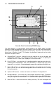
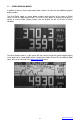
1.6 THE GRAPHICS LCD DISPLAY
Recorder Front View showing TREND Display
The above diagram is a representation of the recorder in the TREND mode. The alpha
characters around the border point to various features of the unit and are described below.
Not shown are the MENUS which pop up over the display. The menus are in the form of
those shown in Sections 4 and 5. The numbers in parenthesis below refer to the section
that covers the topic in detail.
A CompactFlash™ card slot – Manually insert the card into the unit to store data and
configuration information. This card can also be used as a means of updating the
firmware in the unit. Cards up to 2 Gigabytes in size can be used.
B Busy LED (Red) – Is on when the unit is recording and blinks rapidly whenever the unit is
accessing the CompactFlash™ card. The LED blinks at 1 second rate if the unit is
triggered but not recording. Do not attempt to remove the card when this light is on.
C Power LED (Green) – Is on during normal operation. If the optional internal battery
pack is present, this LED will blink during power failure to indicate the unit is running
off internal batteries.
D Optional USB interface – enables connection to a Windows XP compatible PC.
E Navigation buttons – are used to set up and navigate around the display. The buttons
are all dual function; the second function is initiated by holding down the MENU button
while pressing one of the other buttons. The second function is printed on each button.
F Date and Time – shows the actual time of day (real time). The time is displayed user
X2
C
B
A
E
H
F
D
J
I
L
M
N
P
K
G
TABLE OF CONTENTS