Installation Instructions 36” Built-In All-Refrigerators and All-Freezers 31-49078-1 224D2601P003 04-15 GE monogram.
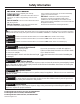
Safety Information BEFORE YOU BEGIN Read these instructions completely and carefully. • If you received a damaged unit, you should immediately contact your dealer or builder. Skill Level – Installation of this unit requires basic mechanical, carpentry and plumbing skills. Proper installation is the responsibility of the installer. Product failure due to improper installation is not covered under the GE Appliance Warranty. See the Owner’s Manual for warranty information.
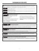
CONSIGNES DE SÉCURITÉ Ce symbole représente une alerte de sécurité. Ce symbole vous avise de dangers possibles pouvant causer la mort, des blessures ou autres. Tous les messages de sécurité seront précédés du symbole d’alerte de sécurité ainsi que des mots « DANGER », « AVERTISSEMENT » ou « MISE EN GARDE ». Ces messages sont les suivants : DANGER Signale une situation qui présente un danger imminent et qui, si elle n’est pas évitée, entraînera des bles sures graves, voire la mort.
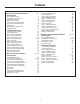
Contents Safety Instructions for Standard Installation Planning Guide The Installation Space Dimensions and Clearances Customization Basics Refrigerator Location 1/4” Framed Panel Dimensions 3/4” Overlay Panel Dimensions Side Panels ZUG2 Grille Panel Dimensions 130° Door Swing Installation Instructions Tools, Hardware, Materials Grounding the Unit Step 1. Remove Packaging Step 2. Install Water Line Step 3. Install Side Panels Step 4. Anti-Tip Procedures Step 5. Level Unit Step 6, Secure Unit to Wall Step 7.
Instructions for Standard Installation 5
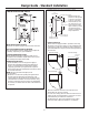
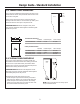
Design Guide - Standard Installation DIMENSIONS AND CLEARANCES THE INSTALLATION SPACE 35" Case Width *83-1/2" at Rear 25-3/8" Case Depth * Shipping height. The product can be adjusted to fit into a cutout that is 84-1/2” max. height. *84" From Note that the top case Floor to trim at the front is 1/2” Top Frame higher and will overlap upper cabinetry or soffit. Use leveling legs and wheels for a maximum 1” height adjustment.
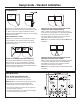
Design Guide - Standard Installation CLEARANCES 130° Door Swing 25" Min. to Wall 2" 15" 130° Clearances for two products installed side-by-side with the same (left or right) door swing Allow 2” minimum clearance between the products to prevent door swing interference. Order the WX14X99 adjustable door stop to reduce the factory set 115° door swing. Allow 15” minimum to a wall to achieve full drawer extension and pan removal. NOTE: ZUG2 and ZUGSS2 Grille Panel Kit will NOT fit this installation.
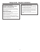
Design Guide - Standard Installation REFRIGERATOR LOCATION CUSTOMIZATION BASICS: Framed or Overlay Panels, Custom Handles and Accessory Kits • Do not install the refrigerator where the temperature will go below 55°F (13°C). It will not run often enough to maintain proper temperatures. • Do not install the refrigerator where temperatures will go above 100°F (37°C). It will not perform properly. • Do not install the refrigerator in a location exposed to water (rain, etc.) or direct sunlight.
Design Guide - Standard Installation 1/4” FRAMED PANEL DIMENSIONS If you choose to install framed panels, they must be cut to the dimensions shown. The panels will slide into the frame on the door and grille. Door If the custom panel is less than 1/4” thick and if it fits loosely in the door frame, it can be backed up with a piece of filler material or foam tape to improve the fit. 5/16" Trim Reveal 1/4" Panel IMPORTANT NOTE: Maximum weight for door panel is 67 pounds.
Design Guide - Standard Installation SIDE PANELS ZUG2 GRILLE PANEL DIMENSIONS Side panels must be used whenever the sides of the unit will be exposed. The 1/4” side panels will slip into the side case trim. Secure the panels to the unit with stickon hook and loop fastener strips. Order the side panels from the cabinet manufacturer. • Cut a notch in the top front corner as shown to allow clearance for corner keys in the front side trim.
Design Guide - Standard Installation Frameless Cabinets: The case trim overlaps cabinets at the top and sides. Therefore, frameless cabinets may require filler strips to prevent interference with cabinet door swing. The opening must allow for filler strips.
Installation Instructions - Standard Installation TOOLS AND MATERIALS REQUIRED GROUNDING THE UNIT • Tin snips to cut banding • #2 Phillips screwdriver • Stepladder • Drill and 1/2”, 3/16” bits • Bucket • 1/4”, 1/2”, 5/16”, 7/16” socket • Level • Safety glasses • Appliance hand truck • Pliers • Tubing cutter • Stud finder • 7/16” and 1-1/4” open-end wrench • 1/4” copper water line tubing or GE SmartConnect™ Refrigerator Tubing kits • Water shut-off valve (optional but recommended) • Custom panels for door
Installation Instructions - Standard Installation STEP 1 REMOVE PACKAGING WARNING • The unit is secured to the skid with 4 slotted tie-down straps. Remove the four 5/16” bolts from the base channels in the tie-downs. • Unit is shipped with two sets of toe kicks. One for Flush Inset (longer) and One for standard installation (shorter). Pick proper toe kick for your installation. Discard other toe kick. • Remove toekick, custom handle trim, and wall bracket. Set aside for final installation.
Installation Instructions - Standard Installation STEP 4 INSTALL ANTI-TIP BRACKET (cont.) STEP 4 INSTALL ANTI-TIP BRACKET WARNING • The anti-tip wall bracket has a series of holes. Select 2 holes that match with the located studs. Make sure the holes selected are on the center of the studs. Mark the wall at these points. Tip Over Hazard. The unit is top-heavy and must be secured to prevent the possibility of tipping forward.
Installation Instructions - Standard Installation STEP 4 INSTALL ANTI-TIP BRACKET (cont.) Install Wall Toggles: The wall toggles and bolts can be ordered as Service Kit #WR49X10193. Wall toggles are installed in the drywall and metal studs for stability. Install the wall toggles as follows: • Drill 1/2” holes at the wall markings made in the holes at the ends of the wall bracket. • Hold the metal channel flat against the plastic straps and slide the channel through the hole.
Installation Instructions - Standard Installation STEP 4 INSTALL ANTI-TIP BRACKET (cont.) Remove Grilles for Access to Anti-Tip Locking Hooks Power Cord Locate the power cord inside the left cavity. If it has not been adjusted so the plug is easily accessible, do so now. Fresh Food Unit • Open the access door. • Remove the 4 screws from the grille. • Pull the bottom of the grille forward, down and out to remove. Freezer Unit • Open the access door. • Remove the 4 screws from the grille.
Installation Instructions - Standard Installation STEP 5 LEVEL UNIT STEP 6 SECURE UNIT TO WALL All models have 4-point leveling. The front is supported by leveling legs; the rear is supported by adjustable wheels. Both are accessible from the front of the unit. • To level the back of the unit, turn the 7/16” hex nut located above the front wheels. Turn clockwise to raise or counterclockwise to lower the unit. • For front leveling, use a 1-1/4” open-end wrench.
Installation Instructions - Standard Installation STEP 7 ADJUST DOOR SWING STEP 8 INSTALL GRILLE PANEL NOTE: This appliance has a 3-position door stop. When space does not allow the door to swing open fully to 115°, you may change the door swing to a 90° opening. A 130° door swing is available for standard installation only. Skip this step if door opening is satisfactory for your installation situation. Pin Location for 90° Door Swing • Raise the access panel to the stop position.
Installation Instructions - Standard Installation Right hand models shown. Use the same instructions for left hand models. IF YOU ARE INSTALLING OVERLAY PANELS, GO TO STEP 10A. STEP 9 INSTALL FRAMED PANELS Handle Trim Door Trim Door Use Front Holes to Secure Trim Use Rear Holes to Secure Handle Install Door Panel: • Open the door to 90°. Remove the 6 Phillips head screws from the door handle. • Remove the handle. Retain all screws. • Remove the 6 screws holding the trim, lift off the trim.
Installation Instructions - Standard Installation Right hand models shown. Use the same instructions for left hand models. STEP 9A INSTALL OVERLAY PANELS Door Trim Handle Trim Door Move Forward For 3/4" Panel Use Front Holes to Secure Handle Use Rear Holes to Secure Trim Supplied handle shown in the overlay panel position. Install Door Panel: • Open the door to 90°. Remove the 6 Phillips head screws from the door handle. • Remove the handle. Retain all screws.
Installation Instructions - Standard Installation STEP 11 START ICEMAKER (FREEZER MODELS ONLY) STEP 10 CONNECT WATER SUPPLY (FREEZER MODELS ONLY) Icemaker House Water Supply Freezer Water Supply Power Switch • Locate and bring the tubing to the front of the cabinet. • Turn the water on to flush debris from the line. Run about a quart of water through the tubing into a bucket, then shut off the water. Copper Tubing: • Slip a 1/4” nut and ferrule (provided) over both ends of the copper tubing.
Instructions for Flush Installation 22
Design Guide - Flush Installation DIMENSIONS AND CLEARANCES THE INSTALLATION SPACE 35" Case Width 39” Finished Width 4-5/16” 5-1/2” Electrical Area 9” *83-1/2" at Rear 26-3/16” Minimum Cutout Depth 85” Finished Opening 75-1/2” From Floor to Bottom of Electrical Area Cold Water Supply 3-1/2” 25-3/8" Case Depth * Shipping height. The product can be adjusted to fit into a cutout that is 85” max. height. Use *84" From leveling legs and wheels Floor to Top Frame for a maximum 1” height adjustment.
Design Guide - Flush Installation CLEARANCES 4" Min. to Wall 1" 15" Min. to Wall 90° Door Swing 115° Door Swing 115° Door Swing 15" Min. to Wall 38-3/4" These units are equipped with a 3-position door stop. The factory set 115° door swing can be adjusted to 90° if clearance to adjacent cabinets or walls is restricted. When Installed into a corner: Allow 15” for a full 115° door swing and pan removal. Allow 4” min.
Design Guide - Flush Installation 1/2” OVERLAY PANEL DIMENSIONS For a more custom appearance, overlay panels may be installed on trimmed models. The overlay panel must be secured to a 1/4” thick backer panel which slides into the trim. A spacer panel 0.10” thick must be placed between the overlay and backer panel. Assemble the panels with glue and screws: • Center the spacer panel on the backer panel, left to right and top to bottom. Secure the panels with glue.
Design Guide - Flush Installation 3/4” DECORATIVE PANEL DIMENSIONS IMPORTANT NOTE: Maximum total weight for the assembled panels: • Door panel – 67 lbs. • Grille Panel – 18 lbs. For a more custom appearance, overlay panels may be installed to give a flush appearance with surrounding cabinets. The overlay panel must be 3/4” thick. Panel attaches to included brackets to provide mounting to the appliance door.
Design Guide - Flush Installation 3/4” RAISED DOOR PANEL ROUTING For 3/4” raised door panel, routing is required. The router depth is 1/4” all the way around the panel back. Additional panel width reductions are required per the diagrams below. This will create a “picture frame” routing that will slide onto the attached door trim. TOP DETAIL TOP NOTE: Routed areas should be finished as they may be visible when assembled.
Design Guide - Flush Installation 3/4” RAISED GRILLE PANEL ROUTING For 3/4” raised grille panel, routing is required. The router depth is 1/4” all the way around the panel back. Additional panel width reductions are required per the diagrams below. This will create a “picture frame” routing that will slide onto the attached grille trim. DETAIL TOP TOP ROUTER DEPTH 1/4” 1-7/16” NOTE: Routed areas should be finished as they may be visible when assembled.
Design Guide - Flush Installation SIDE PANELS ZUG2 GRILLE PANEL DIMENSIONS Side panels must be used whenever the sides of the unit will be exposed. The 1/4” side panels will slip into the side case trim. Secure the panels to the unit with stick-on hook and loop fastener strips. Order the side panels from the cabinet manufacturer. • Cut a notch in the top front corner as shown to allow clearance for corner keys in the front side trim. * Depending on installation height.
Installation Instructions - Flush Installation TOOLS AND MATERIALS REQUIRED GROUNDING THE UNIT • Tin snips to cut banding • #2 Phillips screwdriver • Stepladder • Drill and 1/2”, 3/16” bits • Bucket • 1/4”, 1/2”, 5/16”, 7/16” socket • Level • Safety glasses • Appliance hand truck • Pliers • Tubing cutter • Stud finder • 7/16” and 1-1/4” open-end wrench • 1/4” copper water line tubing or GE SmartConnect™ Refrigerator Tubing kits • Water shut-off valve (optional but recommended) • Custom panels for door and
Installation Instructions - Flush Installation STEP 1 REMOVE PACKAGING WARNING Tip Over Hazard. Product is much heavier at the top than at the bottom – be careful when moving. When using a hand truck, handle from side only. AVERTISSEMENT Risque de basculement Le produit est beaucoup plus lourd en haut qu’en bas. Il faut être prudent lors des déplacements. Si un diable est utilisé, il faut soulever le réfrigérateur sur le côté seulement. • Carefully cut banding at the top and bottom, remove outer carton.
Installation Instructions - Flush Installation STEP 4 INSTALL CASE TRIM STEP 5 INSTALL ANTI-TIP BRACKET (cont.) The unit arrives with case trim for standard installation attached. Flush installation case trim is provided. Remove the factory installed case trim. Install new case trim using supplied right hand and left hand case trim pieces and case trim screws. Attach case trim to each side of case as shown in illustration using case trim screws in holes provided down each side of the case.
Installation Instructions - Flush Installation STEP 5 INSTALL ANTI-TIP BRACKET (cont.) Install Screws and Bolts: • Have someone hold the wall bracket centered in place with each of the holes aligned with the correct opening in the bracket and level with the horizontal line. • Insert the lag screws through the bracket and into the stud. Tighten with a wrench. • Mark an additional hole at each end of the bracket.
Installation Instructions - Flush Installation STEP 5 INSTALL ANTI-TIP BRACKET (cont.) Remove Grilles for Access to Anti-Tip Locking Hooks Fresh Food Unit • Open the access door. • Remove the 4 screws from the grille. • Pull the bottom of the grille forward, down and out to remove. Freezer Unit • Open the access door. • Remove the 4 screws from the grille. • Pull the bottom of the grille forward, down and out to remove. Power Cord Locate the power cord inside the left cavity.
Installation Instructions - Flush Installation STEP 7 ADJUST DOOR SWING STEP 8 INSTALL GRILLE PANEL NOTE: This appliance has a 3-position door stop. When space does not allow the door to swing open fully to 115°, you may change the door swing to a 90° opening. Skip this step if door opening is satisfactory for your installation situation. • Raise the access panel to the stop position.
Installation Instructions - Flush Installation STEP 9 INSTALL OVERLAY PANELS Custom Handles • Custom handles must be used for flush installation. The handle must be properly secured to the overlay panel before sliding the panel into the trim. • The cabinet manufacturer will supply the custom handle and hardware. • Discard the supplied handle. • Slide assembled door panel into the trim. Use Front Holes to Secure Handle Use Rear Holes to Secure Trim Install door panels: • Open door to 90°.
Installation Instructions - Flush Installation STEP 10 CONNECT WATER SUPPLY (FREEZER MODELS ONLY) STEP 11 START ICEMAKER (FREEZER MODELS ONLY) Icemaker House Water Supply Freezer Water Supply Power Switch • Locate and bring the tubing to the front of the cabinet. • Turn the water on to flush debris from the line. Run about a quart of water through the tubing into a bucket, then shut off the water. Copper Tubing: • Slip a 1/4” nut and ferrule (provided) over both ends of the copper tubing.
Instructions for Stainless Steel Installation 38
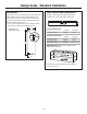
Design Guide - Stainless Steel Installation DIMENSIONS AND CLEARANCES THE INSTALLATION SPACE 35" Case Width *83-1/2" at Rear 25-3/8" Framed Models 25-3/4" Stainless Steel Models Case Depth *84" From Floor to Top Frame * Shipping height. The product can be adjusted to fit into a cutout that is 84-1/2” max. height. Note that the top case trim at the front is 1/2” higher and will overlap upper cabinetry or soffit. Use leveling legs and wheels for a maximum 1” height adjustment.
Design Guide - Stainless Steel Installation CLEARANCES 130° Door Swing 25" Min. to Wall 2" 15" 130° Clearances for two products installed side-by-side with the same (left or right) door swing Allow 2” minimum clearance between the products to prevent door swing interference. Order the WX14X99 adjustable door stop to reduce the factory set 115° door swing. Allow 15” minimum to a wall to achieve full drawer extension and pan removal. NOTE: ZUG2 and ZUGSS2 Grille Panel Kit will NOT fit this installation.
Design Guide - Stainless Steel Installation CUSTOMIZATION BASICS: Custom Handles and Accessory Kits REFRIGERATOR LOCATION • Do not install the refrigerator where the temperature will go below 55°F (13°C). It will not run often enough to maintain proper temperatures. • Do not install the refrigerator where temperatures will go above 100°F (37°C). It will not perform properly. • Do not install the refrigerator in a location exposed to water (rain, etc.) or direct sunlight.
Design Guide - Stainless Steel Installation Frameless Cabinets: The case trim overlaps cabinets at the top and sides. Therefore, frameless cabinets may require filler strips to prevent interference with cabinet door swing. The opening must allow for filler strips.
Installation Instructions - Stainless Steel Installation GROUNDING THE UNIT TOOLS AND MATERIALS REQUIRED • Tin snips to cut banding • #2 Phillips screwdriver • Stepladder • Drill and 1/2”, 3/16” bits • Bucket • 1/4”, 1/2”, 5/16”, 7/16” socket • Level • Safety glasses • Appliance hand truck • Pliers • Tubing cutter • Stud finder • 7/16” and 1-1/4” open-end wrench • 1/4” copper water line tubing or GE SmartConnect™ Refrigerator Tubing kits • Water shut-off valve (optional but recommended) • Screws to secure
Installation Instructions - Stainless Steel Installation STEP 1 REMOVE PACKAGING WARNING Tip Over Hazard. Product is much heavier at the top than at the bottom – be careful when moving. When using a hand truck, handle from side only. AVERTISSEMENT Risque de basculement Le produit est beaucoup plus lourd en haut qu’en bas. Il faut être prudent lors des déplacements. Si un diable est utilisé, il faut soulever le réfrigérateur sur le côté seulement.
Installation Instructions - Stainless Steel Installation STEP4 INSTALL ANTI-TIP BRACKET (cont.) • The kit supplied with the unit contains 2 lag bolts and 4 toggles with bolts. The wall bracket will be attached to the wall in 4 places. • Measure the opening where the unit is to be installed. Mark the center with a vertical line. • Measure up 81 1/2” from the floor. Mark this point on the wall. • Using a level, draw a horizontal line on the wall at this height. • Locate at least 2 studs on the back wall.
Installation Instructions - Stainless Steel Installation STEP 4 INSTALL ANTI-TIP BRACKET (cont.) • Gently pull back at the ends of the plastic straps to make the channel rest flush behind the wall. • Hold the ends of the straps in one hand and slide the plastic cap along the straps until the flange of the cap is flush with the wall. Cap Remove Grilles for Access to Anti-Tip Locking Hooks Fresh Food Unit • Open the access door. • Remove the 4 screws from the grille.
Installation Instructions - Stainless Steel Installation STEP 4 INSTALL ANTI-TIP BRACKET (cont.) STEP 5 LEVEL UNIT All models have 4-point leveling. The front is supported by leveling legs; the rear is supported by adjustable wheels. Both are accessible from the front of the unit. • To level the back of the unit, turn the 7/16” hex nut located above the front wheels. Turn clockwise to raise or counterclockwise to lower the unit. • For front leveling, use a 1-1/4” open-end wrench.
Installation Instructions - Stainless Steel Installation STEP 7 ADJUST DOOR SWING STEP 6 SECURE UNIT TO WALL NOTE: This appliance has a 3-position door stop. When space does not allow the door to swing open fully to 115°, you may change the door swing to a 90° opening. A 130° door swing is available for standard installation only. Skip this step if door opening is satisfactory for your installation situation.
Installation Instructions - Stainless Steel Installation STEP 9 START ICEMAKER (FREEZER MODELS ONLY) STEP 8 CONNECT WATER SUPPLY (FREEZER MODELS ONLY) Icemaker House Water Supply Freezer Water Supply Power Switch • Locate and bring the tubing to the front of the cabinet. • Turn the water on to flush debris from the line. Run about a quart of water through the tubing into a bucket, then shut off the water. Copper Tubing: • Slip a 1/4” nut and ferrule (provided) over both ends of the copper tubing.
Notes 50
Notes 51
NOTE: While performing installations described in this book, safety glasses or goggles should be worn. For Monogram® local service in your area, call 1.800.444.1845. NOTE: Product improvement is a continuing endeavor at General Electric. Therefore, materials, appearance and specifications are subject to change without notice. 31-49078-1 224D2601P003 04-15 GE Printed in the United States GE Appliances Appliance Park Louisville, KY 40225 GEAppliances.