
Installation Instructions


31-49140
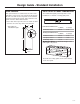
Design Guide - Standard Installation
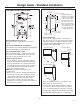
36" Frame to
Frame Width
*84" From
Floor to
Top Frame
35"
Case Width
*83-1/2"
at
Rear
25-3/8" Case Depth
Depth Including
Handles 26-7/8"
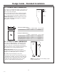
THE INSTALLATION SPACE
Water And Electrical Locations
Electrical and water supply must be located as
shown.
The Cutout Depth Must Be 24” Minimum
The unit will project forward, slightly beyond adjacent
cabinetry, depending on your installation.
Cutout Depth Beneath a Soffit:
When installed beneathh a soffit, the soffit cannot
exceed the 24” installation depth shown. The top
case trim overlaps the bottom of the soffit.
Additional Specifications
• A 115 volt 60Hz., 15 or 20 amp power supply is
required. An individual properly grounded branch
circuit or circuit breaker is recommended. Install
a properly grounded 3-prong electrical receptacle
recessed into the back wall. Electrical must be
located on rear wall as shown.
NOTE: GFI (ground fault interrupter) is not
recommended.
• Water line can enter the opening through the floor
or back wall. The water line should be 1/4” O.D.
copper tubing or QuickConnect
™
kit between the
cold water line and water connection location,
long enough to extend to the front of the unit.
Installation of an easily accessible shut-off valve in
the water line is required.
DIMENSIONS AND CLEARANCES
* Shipping height. The
product can be adjusted
to fit into a cutout that
is 84-1/2” max. height.
Note that the top case
trim at the front is 1/2”
higher and will overlap
upper cabinetry or soffit.
Use leveling legs and
wheels for a maximum
1” height adjustment.
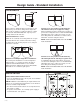
Product Clearances
These units are equipped with a 3-position door
stop. The factory set 115° door swing can be adjust-
ed to 90° if clearance to adjacent cabinets or walls
is restricted. Order WX14X99 door stop for precise
settings between 90° and 130°.
130° Door Swing
90° Door Swing
90° Door Swing
4” Minimum
to a Wall
90°
23-7/8”
Case Behind
Frame
36-3/4”
Allow 25” minimum clearance for a full 130° door
swing. Allow 15” for pan removal.
For a 90° door swing, allow 4” minimum clearance
to a wall. If the 90° doorstop position is used, pan
access is maintained but pan removal is restricted.
See illustration on page 11 to determine door swing
interaction with adjacent cabinets or countertops.
115° Door Swing
6