Owner’s Guide and Installation Manual 3AVMR64XXD Series Fan ETL Model NO. : 3AVMR64XXXXX Attach sales receipt to this card and retain as your proof of purchase DATE OF PURCHASE: RETAILER NAME: MODEL NUMBER: RETAILER ADDRESS: To register your fixture, please visit our website www.montecarlofans.com 7.95 kgs 17.
Cautions and Warnings WARNING: TO REDUCE THE RISK OF FIRE, ELECTRIC SHOCK, OR INJURY TO PERSONS, OBSERVE THE FOLLOWING READ AND SAVE THESE INSTRUCTIONS Installation work and electrical wiring must be done by qualified person(s) in accordance with applicable codes and standards (ANSI/NFPA 70-1999), including fire-rated construction. Use this unit only in the manner intended by the manufacturer. If you have any questions contact the manufacturer.
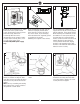
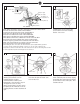
1 2 ON 3 ON Mounting bracket OFF OFF Before you begin installing the fan, Switch power off at Service panel and lock service disconnecting means to prevent power from being switched on accidentally. When the service disconnecting means cannot be locked, securely fasten a warning device, such as a tag, to the service panel. Use AC 120V/60HZ power supply only. 4 Wood screw Before installing this fan make sure the outlet box is properly installed to the house structure.
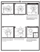
7 8 9 Lead wire Downrod Downrod Safety cable Canopy Canopy bottom cap Yoke Set screws Canopy Downrod Keeper pin Canopy bottom cap Yoke cover Yoke cover Cross pin Remove preassembled keeper pin and cross pin from downrod. 10 Place downrod over canopy, canopy bottom cap and yoke cover. Partially loosen downrod set screws from yoke at top of motor assembly. Thread lead wires and safety cable from motor assembly through downrod.
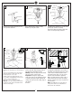
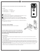
13 Wall Switch Black (Live) 14 Power source White (Neutral) Blue (For Light) Ground/Green White (For Light) Red (Motor 1) Purple (Motor 2) Gray (Motor 3) Green/Ground Receiver White (AC IN N) Black (AC IN L) Make wiring connections using wire connectors provided as indicated above. Red from fan to Red from remote marked Motor 1. Purple from fan to Purple from remote marked Motor 2. Gray from fan to Gray from remote marked Motor 3. Blue from fan to Blue from remote marked FOR LIGHT.
18 19 Install LED Light Kit 20 Light pan LED light kit Reinstall the screw removed in step 16. Tighten all screws securely. Remove 3 preassembled screw from the light pan. Save screws for later use. Connect white wire from fan to white wire from LED light kit and then connect blue wire from fan to blue wire from LED light kit. Note: If you don’t want to install the fan with LED light, go to step 23 for blanking plate installation.
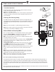
REMOTE CONTROL SETTING and OPERATION Transmitter Operation Remove the battery cover from the remote control transmitter and install battery, battery provided. Replace the cover. Note: Use 2 1.5V/AAA battery. Note: If not using for long period of time, remove battery to prevent damage to remote transmitter, and store the remote transmitter away from excess heat or humidity.
The buttons on the remote control transmitter control the fan speed and light as follows. Fan speed 1 = minimum speed 3 = medium low speed 5 = medium high speed 2 = low speed 4 = medium speed 6 = high speed This button turns the fan off. Forward/Reverse button- This button is to control direction of fan rotation. Press once to change direction of the fan rotation. Fan must be running to reverse. Light button- Press this button to turn light on or off.
Trouble Shooting ,I \RX KDYH GLI¿FXOW\ RSHUDWLQJ \RXU QHZ FHLOLQJ IDQ LW PD\ EH WKH UHVXOW RI LQFRUUHFW DVVHPEO\ LQVWDOODWLRQ RU ZLULQJ ,Q VRPH FDVHV WKHVH LQVWDOODWLRQ HUURUV PD\ EH PLVWDNHQ IRU GHIHFWV ,I \RX H[SHULHQFH DQ\ IDXOWV SOHDVH FKHFN WKLV 7URXEOH 6KRRWLQJ &KDUW ,I D SUREOHP FDQQRW EH UHPHGLHG RU \RX DUH H[SHULHQFLQJ GLI¿FXOW\ LQ LQVWDOODWLRQ SOHDVH FDOO RXU &XVWRPHU 6HUYLFH &HQWHU DW WKH QXPEHU SULQWHG RQ \RXU SDUWV OLVW LQVHUW VKHHW Warning %HIRUH VHUYLFLQJ RU FOHDQLQJ XQL
Nov.