
Instructions / Assembly


4
© 2014 Monte Carlo Fan Company
11/1/2014
7 8 9
10 11 12
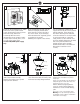
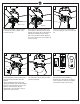
Install ball end of downrod into mounting
bracket opening. Align (engage) slot on
ball with tab on mounting bracket.
Warning: Failure to align slot on ball with
tab may result in serious injury.
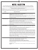
For Canadian installation and for USA fan
and light kit combinations over 35 lbs, in
both flush and downrod modes the safety
cable must be installed into the house
structure beams using 3” lag screws,
washers and lock washers provided.
Make sure that when the safety cable is
fully extended the lead wires are longer
than the cable and no stress is placed on
the lead wires.
Note: If Installing The Secondary Support
Safety Cable in the U.S., Do Not Remove
Knockouts In The Outlet Box.
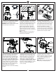
Set dip switches on the Remote
Transmitter and Remote Receiver to the
same settings. This must be done so the
units will communicate properly. If you
have other fans you can set to control
from one Transmitter by setting
receivers the same as the Transmitter. If
you have more than one fan with remote,
you can set the dip switches to different
positions to have separate control.
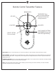
Make wiring connections using wire
connectors provided as indicated above.
White from fan to White from remote
marked N. Black from fan to Black from
remote marked L. Blue from fan to Blue
from remote marked FOR LIGHT. White
from house to White from remote marked
AC N. Black from house to Black from
remote marked AC L. Connect all green
grounded wires to Grounded wire from
House. Make sure that no filaments are
outside of the wire connectors.
Insert the remote receiver into mounting
bracket.
Partially loosen 2 of the set screws on
mounting bracket corresponding to the
slotted holes on the canopy upper ring.
Remove the other 2 set screws. Save
screws. Lift fan to mounting bracket,
aligning the “L” shape holes with the
screws on the mounting bracket. Turn the
fan clockwise to lock in position. Install
the other 2 canopy mounting set screws
which were removed and tighten all
screws securely.
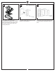
Insert blade into the slot on flywheel.
Install blade with screws and fiber
washers provided, aligning each of the
holes as shown and tighten all screws
securely. Repeat this process for
remaining blades.
Note: Make sure the side with a label
“This side up” is installed upward.
SAFETY CABLE INSTALLATION
Dip switches
Lag screw
Safety cable
Washer
Lock washer
ON
Tab
Slot
Wall switch
White
White
Blue
Black
Black
Receiver
Ground/Green
Black
(Live)
White
(Neutral)
Power
source
This side up
This side up
Blade