Owner’s Guide and Installation Manual 3MAVR52XXD Series Fan CUL Model NO. : 3MAVR52XXD Attach sales receipt to this card and retain as your proof of purchase DATE OF PURCHASE: RETAILER NAME: MODEL NUMBER: RETAILER ADDRESS: To register your fixture, please visit our website www.montecarlofans.com 5.7 kgs 12.
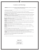
Cautions and Warnings WARNING: TO REDUCE THE RISK OF FIRE, ELECTRIC SHOCK, OR INJURY TO PERSONS, OBSERVE THE FOLLOWING READ AND SAVE THESE INSTRUCTIONS Installation work and electrical wiring must be done by qualified person(s) in accordance with applicable codes and standards (ANSI/NFPA 70), including fire-rated construction. Use this unit only in the manner intended by the manufacturer. If you have any questions contact the manufacturer.
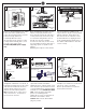
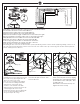
1 2 3 Ceiling joist Ceiling Outlet Box ON ON Ceiling Joists OFF Mounting Bracket Screw/ Washers /Spring Washers OFF 2˝ x 4˝ Outlet Box Before you begin installing the fan, Switch power off at Service panel and lock service disconnecting means to prevent power from being switched on accidentally. When the service disconnecting means cannot be locked, securely fasten a warning device, such as a tag, to the service panel. Use AC 120V/60HZ power supply only.
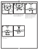
7 8 9 Downrod Canopy Canopy ring Cross pin Screwdriver Yoke cover Place downrod over canopy, canopy ring and yoke cover. Thread lead wires and safety cable from motor assembly through downrod. For easy installation of cross ping on next step. 10 11 12 Carefully insert a phillips screwdriver through yoke and downrod (don’t damage the lead wires) as a guide and then push the cross pin and pull the screwdriver in the meantime as shown in illustration.
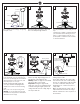
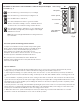
13 To Motor U- Red To Motor V- Purple To Motor W- Brown To Light White To Light Blue White (Neutral) Receiver Black (Live) Wall Switch Black- AC IN L Green or Bare Ground White- AC IN N Light Blue Motor U- Red Motor V- Purple Motor W- Brown Light White Green From Hanger Ball Green From Mounting Bracket Receiver 120V Supply (Power Supply) Make wiring connections using wire connectors provided as indicated above. Red from fan to Red from receiver marked Motor U.
17 18 19 LED light fixture Loosen 2 and remove 1 preassembled screw from light pan. Save screw for later use. Connect light lead wires from fan to the lead wires from LED light fixture with quick connectors. Make sure the quick connectors are firmly clasped. Attach LED light fixture onto the light pan, aligning the keyhole slots on the LED light fixture with the preassembled screws on the light pan. Twist clockwise till lock. Reinstall the screw removed in step 17. Tighten all screws securely.
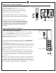
REMOTE CONTROL SETTING and OPERATION Remove the battery cover from the remote control transmitter and install battery. Replace the cover. Note: Use 2 1.5V/AAA battery to replace battery. (Fig. 1) Note: If not using for long periods of time, remove battery to prevent damage to remote transmitter, and store the remote transmitter away from excess heat or humidity. Install Transmitter wall mount cradle with 2 screws provided.
The buttons on the remote control transmitter control the fan speed and light as follows. (Fig. 4) LED Indicator UP Speed Press the button to get desired fan speed, Low to High. Press the button to get desired fan speed, High to Low. Down Speed Press the OFF button to turn fan off. Turn Fan Off Press this forward/reverse button to get desired airflow direction. Fan must be running to reverse. It will take about 25 seconds for fan to slow down and change rotation direction.
Trouble Shooting or wiring. In some cases, these installation errors may be mistaken for defects. If you experience any faults, installation, please call our Customer Service Center at the number printed on your parts list insert sheet. Warning means to prevent power from being switched on accidentally. When the service disconnecting means cannot be locked, securely fasten a prominent warning device, such as a tag, to the service panel. Trouble 1. If fan does not start: Suggested Remedy 1.
Nov.