
Use and Care Guide


5
© 2018 Monte Carlo Fan Company
10/2018
13
14 15 16
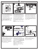
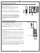
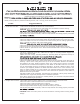
Make wiring connections using wire connectors provided as indicated above.
Red from fan to Red from receiver marked Motor U.
Purple from fan to Purple from receiver marked Motor V.
Brown from fan to Brown from receiver marked Motor W.
White from fan marked “For light” to White from receiver marked “For light”.
Blue from fan marked “For light” to Blue from receiver marked “For light”.
White (Neutral) from house to White from remote marked AC IN N.
Black (Live) from house to Black from remote marked AC IN L.
Connect all green grounded wires to Grounded wire from House.
Make sure that no filaments are outside of the wire connectors.
Insert the remote receiver into mounting bracket.
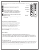
After making the wire connections, the wires should be spread apart with the grounded conductor and the equipment-grounding conductor on one
side of the outlet box and ungrounded conductor on the other side of the outlet box. The splices after being made should be turned upward and
pushed carefully up into the outlet box.
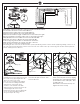
Partially loosen 2 of the set screws on
mounting bracket corresponding to the slotted
holes on the canopy upper ring. Remove the
other 2 set screws. Save screws.
Raise canopy to mounting bracket, aligning
loosened screws in mounting bracket with
slotted holes in canopy. Twist canopy
clockwise to lock. Reinstall screws (with
washers) that were previously removed in step
3 and then tighten all screw securely
Install canopy ring onto canopy by aligning the
grooves in canopy ring with the humps on
canopy and snap it onto canopy.
Hump
Groove
Green From Hanger Ball
Green From Mounting Bracket
Motor U- Red
Motor V- Purple
Motor W- Brown
Receiver
White- AC IN N
Black- AC IN L
Green or Bare Ground
Wall Switch
120V Supply
(Power Supply)
To Motor U- Red
To Motor V- Purple
To Motor W- Brown
Black (Live)
White (Neutral)
Light White
Light Blue
To Light White
To Light Blue
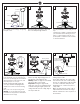
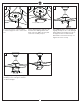
Loosen 2 and remove 1 preassembled
screw from the plate on motor. Save
screw for later use.
Place light pan over the lead wires and
attach it onto the plate on motor, aligning
the keyhole slots on the light pan with the
preassembled screws on the plate. Twist
clockwise till lock.
Reinstall the screw removed in step 15.
Tighten all screws securely.
Receiver
Plate on motor
Canopy ring
Light pan