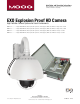
Installation and Operation Instructions Before attempting to connect or operate this product, please read these instructions completely. EXO Explosion Proof HD Camera High Definition Camera Systems for Harsh Environments EXPD7C1-2................Purged 1080P HD PTZ camera system, 20x optic zoom, H.264 support, ONVIF: Class I Division 2 Groups A, B, C and D EXPD7C1-3................Purged 1080P HD PTZ camera system, 20x optic zoom, H.264 support, ONVIF: Class I Division 2 Groups A, B, C and D EXPD7C2-2.....
IMPORTANT SAFEGUARDS 1 Read these instructions. 2 Keep these instructions. 3 Heed all warnings 4 Follow all instructions. 5 Do not use this apparatus near water. 6 Clean only with damp cloth. 7 Do not block any of the ventilation openings. Install in accordance with the CAUTION RISK OF ELECTRIC SHOCK DO NOT OPEN manufacturers instructions. 8 9 SAFETY PRECAUTIONS Cable Runs- All cable runs must be within permissible distance.
Product Warranty Registration Register Your Products Online www.moogS3.com/technical-support/product-registration Moog values your patronage. We are solely committed to providing you with the highest quality products and superior customer service. With 3-Year and 5-Year warranties (depending on the product purchased) we stand behind every product we sell. See full warranty details at www.moogS3.
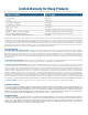
Limited Warranty for Moog Products Moog - Decatur Operations, subsequently referred to as “Manufacturer,” warrants these products to be free from defects in material or workmanship as follows: PRODUCT CATEGORY PARTS \ LABOR All Enclosures and Electronics Five (5) Years Accessory Brackets Five (5) Years Controllers Three (3) Years Power Supplies / IR Illuminators Three (3) Years Poles / PolEvators™ / CamEvator Three (3) Years Warrior Series™ / Q-View™ Three (3) Years SView Series Three (3) Ye
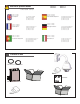
! Electrical Specifications EXPD7C1-2 EXPD7C2-2 EXPD7C1-3 EXPD7C2-3 115 VAC or 230 VAC - Power Input 115 VAC / .75 Amps 230 VAC / .36 Amps Tools Required: English 115 VAC / .75 amperios 230 VAC / .36 amperios .100” Flat Head Screwdriver Phillips Head Screwdriver 7/16” Wrench or Socket 9/16” Wrench or Socket Las Herramientas Requirieron: Español 115 VAC / .75 Ampere 230 VAC / .36 Ampere 115 VCA / .75 ampères 230 VCA / .
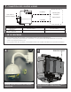
1 Unit is shipped with 100’ (max) flex tubing (3/8” & 1/4”) to connect enclosure to purge pressurized unit. 2 fitting are provided as shown in the diagrams.
3 English NOTES • To ensure adequate protective gas flow to the protected enclosure, all piping and tubing must be fully reamed. • Precaution must be taken to prevent crimping and other damage to protective gas piping and tubing. Caution must be used when opening/closing swing panel to prevent tubing kinks. • Supplied 1/4” & 3/8” Poly Tubing have ferrule, nut & insert preset. Use that end for connecting to power box.
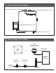
5 TUBING CONNECTION DIAGRAMS ENCLOSURE SUPPLY OUTLET ENCLOSURE REFERENCE INLET PEPPERL+ FUCHS PURGE/PRESSURIZATION UNIT SYSTEM SUPPLY INLET 6 TUBING CONNECTION DIAGRAMS DOME PRESURE GAUGE [ENCLOSURE] EXP PRESURE SWITCH ATMOSPHERIC REFERENCE SDOEN OF WOSTOE .3 .2 .1 .4 SAFE 0 HIGH LOW .
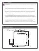
7 CONNECTION SIZES, LENGTHS & BENDS CAMERA PEPPERL+ FUCHS REFERENCE GAS SUPPLY (System Supply) PROTECTED CAMERA ENCLOSURE CAMERA PURGE/PRESSURIZATION UNIT SUPPLY System Supply 3/8” OD SS Tubing Fully Reamed MAXIMUM: 20 ft / 10 bends Camera Supply Camera Reference SUPPLIED 3/8” Poly Tubing SUPPLIED 1/4” Poly Tubing 100 ft MAX 100 ft MAX SET-UP PROCEDURE • See supplied Model 1001A Installation and Operation Manual for Class I Purging Set-up.
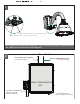
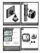
11 WALL MOUNT: Attach unit securely to the wall mount using (4) 3/8” or 8mm hardware (not supplied). 12 INPUT: (120VAC 1A 240VAC .5A) The power box may be pole mounted with the pole support clips. (Stainless steel straps not provided). 13 220-240VAC INPUT (.36Amps) 110-120VAC INPUT (.75Amps) 240Vac 120Vac Input Input The box is designed for either 120 or 240 VAC input single phase.
14 OUTPUT: (24VAC 84VA) CAMERA and HEATERS Housing Power (Connected at Factory) 75 WATTS MAX 24Vac Power To Housing Optional 24Vac Output Main Switch Internal resettable fuses are supplied for the main 24VAC output lines. Do not connect heaters to camera output. The PB24 is not designed for 3 phase or 208V systems.
Part Number Replacement Parts List 1 or 2 3 Description 1 RP65EXPT-2000 PAN TILT (20x HD) 2 RP65EXPT-3000 PAN TILT (30x HD) 3 PR25DCP74010 TRIM RING ASSEMBLY WITH CLEAR DOME
TABLE OF CONTENTS Software Sections Moog Discovery Tool ...................................................... ..................................................................................................... 1.0.0 Using the Moog EXO Web Application ............................. ..................................................................................................... 2.0.0 System Status ............................................................... .....................................
SOFTWARE SETUP 1.0.0 Moog Discovery Tool By factory default, the Moog EXO Camera is configured in DHCP. If you are not using a DHCP server it will automatically allocate itself an APIPA (Automatic Private IP Addressing) address in the range 169.254.0.1 to 169.254.255.254 with subnet mask 255.255.0.0. Initial device network configuration is done via the Moog Discovery Tool (MDT), a tool provided by Moog that can be found on the company’s web site and on the flash drive supplied with each camera system.
To configure the Unicast Discovery, add one or more IP address ranges. The Unicast Discovery tries to reach a device at a specific IP address in the configured ranges. The discovery can be a long process if the range of IP addresses is large and the device is at the end of the range. To accelerate the discovery, add several small ranges of IP addresses. The ping timeout option can be increased for a high latency network.
To assign IP Address, update firmware, or configure Moog web interface, right click on highlighted serial number / Mac Address. Assign IP Address(es) Once the IP information is set, the Silverlight web application served by the EXO Camera can be launched from the MDT or directly in your web browser by typing the device’s IP address in the address bar.
2.0.0 Using the Moog EXO Web Application Application When entering the Web Application, the following window will be displayed. You will be asked a username and password. The default User name and Password is ‘admin’.
2.1.0 System Status Status Window System Status - 2.1.0 Configuration - 2.2.0 Main Menu Tabs Maintenance - 3.0.0 Live Viewer - 4.0.0 Recording - 5.0.0 Upon successfully logging into the web interface, a welcome screen will be displayed. The welcome screen shows general device health status as well as firmware version and system uptime.
2.2.0 System Configuration Configuration / System Under the Configuration section, select the System tab to perform the following operations: • View product model information, current firmware version and serial number. • Specify a custom name; this name can be used by third-party software to display a selected name for the device. - Enable edge recording by checking the box “Use Recorder Module” checkbox. Disabling edge recording will accelerate the device’s boot time.
2.2.1 Configuration / Date Time Under the Configuration section, select the Date Time tab to perform the following operations: • Set the time zone in which the device is operating. • Manually set the current date and time for the device’s internal clock. • Note: For an accurate time stamp, you must sync UTC Time. 2.2.
2.2.3 Configuration / Network / DHCP Under the Configuration section, select the Network tab to perform the following operations: • Set the encoder’s IP parameters; DHCP or static IP information. • Configure an NTP server to allow the device to automatically update its internal clock using an NTP server. 2.2.4 Configuration / Network / Host Name Configuration-NPT NPT Server- use when desiring to have local network time as default, to do so you must……. 2.2.
2.2.6 Configuration / Network / API- Boujour NOTE: • To control the EXO Camera system with a VMS software system, you must enable the required Network APIs. Enable PSIA or GENETEC API depending on which VMS platform you intend to use with the device. Disabling any unrequired APIs will accelerate boot time. • Note: ONVIF standard is built in and does not require activation. If using ONVIF you do not need to select an API. • Set Bonjour discovery protocol settings.
2.3.0 Configuration / Video In 2.3.1 Configuration / Video In / Video Input Under the Configuration section, select the Video In tab to perform the following operations: Digital format – choices are, 720 30fps, 720 60fps, 1080 30fps, 1080 25fps. Note max camera output with WDR Active is 15fps (1080p). 2.3.2 Configuration / Video In / Sensor Configure camera bloc / sensor parameters.
(Note: Activating WDR at 1080P will reduce maximum frame rate to 15fps.) Configure video compression parameters for any of the three available codec instances (Primary H.264, Secondary H.264 and MJPEG). Most VMS software solutions will interact with these parameters and thus it is suggested to leave these at default values in the web interface. VBR aggressiveness however is unique to Moog EXO Cameras and proposes various levels (disabled to aggressive) of motion triggered rate control.
2.3.4 Configuration / Video In / Point to Point • Configure point to point video connections (up to three) for creating persistent video streams from the encoder to a network endpoint. 2.3.5 Configuration / Video In / Text Overlay Text Box To insert a text overlay: • There are (2) available strings (Text blocks). Select string. • Select string size. • For string position click mouse inside string position box. o Text bar will appear on video image.
2.3.6 Configuration / Video In / Motion Detection Select from 1 of 4 available regions: • With mouse click on region position box. • Bring mouse pointer to view window and drag box around area for motion detection. • Select desired Frame Count, Sensitivity and Thresholds. • Press “Save” button to store information. • You can select up to (4) separate “Motion” windows.
2.3.7 Configuration / Video In / Privacy Zones Privacy Zones are used to block out video in areas view is not permitted or desired. To add a Privacy Zone: • Select the Zone to be identified with privacy area. There are up to 16 zones available. • With the mouse, click on Privacy Zone Position Box. • Move mouse pointer over the Image Window, click and draw a box on the area you wish to see video. • Press the “Save” button to store.
2.3.8 Configuration / Audio In Under the Configuration section, select the Audio In tab to perform the following operations: • Configure audio input compression parameters. • Configure point to point audio connections (up to three) for creating persistent audio streams from the encoder to a network endpoint.
2.3.9 Configuration / Audio Out Under the Configuration section, select the Audio Out tab to perform the following operations: • Configure audio output parameters. • Configure a point to point audio connection for receiving a persistent audio stream from a network endpoint.
2.4.
Note: Recording Menu will NOT be visible unless activated; see 2.20 System configuration. • Grooming mode; Select method to remove files from full SD card chronological will remove old files first.
2.4.1 Configuration / User Accounts Under the Configuration section, select the User Accounts tab to perform the following operations: • Select the web interface’s authentication method. A dual passphrase is made available for additional security. • Manage user accounts which have access to the device.
3.0.0 Maintenance This section describes how to update your Moog EXO Cameras to newer firmware versions from the web application. 1. To find the latest file go to www.moogS3.com/technical-support/. 2. Click on “EXO PTZ Camera Firmware” - click, save file. 3. Navigate to your device’s web application using your favorite web browser. 4. Click on the Maintenance tab. 5. Click on the Update button, locate downloaded firmware. You will be asked for the firmware update file; please select the .
4.0.0 Live Viewer Use Live View for: • Live Camera View • Start and Stop Recording • Pan / Tilt and Camera Control • Setting Presets • Adjust View Scale To enable live you must activate by pressing the “Play” button. Play Button To adjust viewing scale for 1024 x 768 monitor, press smaller view.
4.1.0 Live Viewer Pan / Tilt and Presets Pan/Tilt Controls Lens Control Preset Controls • Pan Tilt Control; To operate Press Arrow in desired direction of movement. • Use Pan / Tilt speed slider controls to vary Pan / Tilt speed control, to increase speed, slide control knob to the right. • Lens Funtion use +/- buttons to update Iris, Zoom and Focus. • Preset Functions. • o First Select Preset Number. o Then position Camera and lens to desired position. o Press “Set” to save Preset.
5.0.0 Recording To activate recording mode you must go to Configuration / System / Use Recorder Mode. Click “Use Recorder Mode” checkbox. This will activate addional Recording controls in the recording window. You must “Save” and then “Reboot” after making this change. > Select Video Input > Select Date of the Recording Then select the filed clip you wish to view Note: You must have either VLC Player or Windows Media Player installed.
6.0.0 Performing Batch Firmware Update This section describes how to perform a batch update of multiple Moog EXO Camera devices to newer firmware versions from the MDT. The batch firmware update works by starting a firmware update session. Only one session at time is allowed and only 20 devices can be selected by session. From the MDT, select one or more devices of the same type. By using the right mouse button on the selected devices, choose the “Firmware Update” menu option.
To start a firmware update session, choose the “.iof” file corresponding to the new firmware by clicking to the “Select File …” button. Once selected, click the “Start” button. Once started, the “Firmware Update Session” window shows the progress of the firmware update. This window can be closed at any moment without losing the current session.
If closed, the progress of the current session can be followed by reopening the “Firmware Update Session” window by clicking the from the “Tools” toolbar. button Once done, clear the current session from the “Firmware Update Session” window and restart a new session if needed. 7.0.0 Point to Point Connections Point-to-point connections between a Moog EXO Camera and a Decoder can be configured using the device’s web application.