PDM Power Distribution Modules USER MANUAL
MoTeC PDM User Manual Contents Introduction ........................................................................ 1 Features................................................................................................... 1 System Overview ..................................................................................... 2 Installation .......................................................................... 3 Mounting .............................................................................
PDM User Manual Standby Mode........................................................................................ 29 Appendices ....................................................................... 30 Specifications......................................................................................... 30 CAN Input Channel Examples ............................................................... 32 Fuse Characteristics ..............................................................................
MoTeC Introduction 1 Introduction The PDMs replace conventional relays, fuses and circuit breakers by providing electronically switched power to the various electrical systems in the vehicle, including motors, lamps, ECUs and data systems. This simplifies wiring and switch requirements, while increasing reliability. There are four PDM versions: PDM16, PDM32, PDM15 and PDM30.
2 Introduction Providing full diagnostic information, including output currents and voltages, input voltages, and error status Transmitting diagnostic information via CAN to a display or data logging device or monitoring directly on a PC Protected against unauthorised access by a password feature.
MoTeC Installation 3 Installation Mounting When mounting the PDM take into account that the PDM may get very hot during operation. Ensure the PDM is mounted in a well ventilated area and not against a hot surface. For case dimensions see Mounting Dimensions. The internal temperature is highly dependent on ambient temperature and also on the total load current—a higher current will cause a higher temperature.
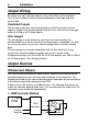
4 Installation Wiring – + Battery Starter Motor Isolator Alternator M A Battery Input Switches Inputs PDM CAN CAN Connector for UTC 0V Outputs CAN Bus Keypad M M ECU Motors Lights Data Logger Other Devices Battery Positive Battery positive is supplied to the PDM via the single pin connector to suit wire sizes 16 mm2 (6#) or 25 mm2 (4#). The PDM16 and PDM32 use an Autosport connector, PDM15 and PDM30 use a 6 mm eyelet to suit the wire size.
MoTeC Installation 5 If the ECU does not have a shutdown input, the switch can be connected to a PDM input. The PDM can then turn off power to the ignition system or the ECU, which will cause the engine to stop. Battery Negative Both of the Batt– pins should be wired to battery negative via 20# wire. These pins normally only carry the very low operating current, however during a load dump they carry the load dump current which may be 50 ampere or higher.
6 Installation Output Wiring All outputs are high side type outputs; they switch Batt+ to the output pin. They all have hardware thermal overload protection, fault logic and overcurrent logic. Paralleled Outputs Two or more output pins can be connected in parallel to increase current capacity. Outputs that are connected in parallel must all be of the same type; either all 8 Amp or all 20 Amp outputs.
MoTeC Installation 7 The wiper unit can be wired using an OEM wiper controller with the PDM supplying the power only. The OEM controller performs the intermittent and motor braking functions. 2. Two Switch Method On Output PDM Slow Off S M c Fast F Home Park Switch The wiper unit can be wired in a simple two switch arrangement; one switch for power and the other to select fast or slow. The PDM supplies power only.
8 Installation Slow operation can be achieved using the switch or using intermittent operation to give a similar effect which avoids the need for a high current switch. The fast/slow switch and on/off relay must handle the wiper motor current (typically 4 ampere). The control switches can be low current types since they only connect to PDM inputs. 4.
MoTeC - Installation braking the motor when the high speed winding is turned on. The linked high speed wiper output can be configured in the Output 9 settings. Output 9 performs motor braking by momentarily shorting the output to ground when the output turns off.
10 Installation - Set the High Time and Low Time to 0.00s in the park switch input pin configuration so that the wiper is parked as soon as possible after reaching the park position. An sample configuration for this method is included with PDM Manager. Note: Version 2 hardware is indicated by the symbol 2 next to the engraved serial number on the PDM case. Solenoids The current drawn by a normal single coil solenoid ramps up from zero to its steady state value over a period of time.
MoTeC Installation 11 Electronic Devices The PDM can supply power to electronic devices such as engine management systems, data acquisition systems, radios etc. Many electronic devices will have a short inrush current. The PDM will largely ignore this due to the Output Load filtering. See the Over-Current Shutdown section for details. The PDM provides reverse battery protection and load dump clamping to protect itself and the connected devices.
12 Installation CAN Keypads The CAN Keypads continuously communicate with the PDM which will prevent the PDM from entering its low power standby mode. Options for powering the keypads include: - Configuring the PDM to always power the keypads. This allows buttons on the keypads to be used for master startup functions, but the PDM would never enter standby mode. To minimize battery drain, the isolator would need to be turned off (eg.
MoTeC Installation 13 To start the program after installation, click Start > All Programs > MoTeC > PDM Manager Updating PDM Manager Software Software updates are available to give access to the latest features. Download the latest software version from the website and follow the software installation instructions to update to the new version. To update the associated firmware in the device select Update Firmware from the Online menu. For more information refer to Operation.
14 Configuration Configuration The PDM requires various settings to be configured such as the maximum current settings for the outputs and the circumstances in which to turn the outputs on. The configuration settings are stored in a configuration file on the PC. Changes to the PDM configuration are performed ‘Offline’, i.e. without the PC communicating with the PDM. The changes are saved in the configuration file on the PC. The file must be sent to the PDM before the changes take effect. See Operation.
MoTeC Configuration 15 Channels Channels are used to link the various systems within the PDM configuration. For example: The input pin system generates two channels for each configured input pin. Depending on the state of the input pin the input channel value will be zero or one. The channel can be selected to directly control a particular output. It can also be used as an input to a Condition. This is a complex logic function that combines a number of channels to create a new channel.
16 Configuration To rename a channel globally Right-click on the channel name in the Channels window and click Rename. This will rename the channel where it is generated as well as in all the places where it is used. Configuration Tree The Configuration Tree is used to configure the Global Setup, Input Pins, CAN Inputs, Conditions, CAN Outputs, Keypad buttons and Output Pins. The input and output pins will be numbered according to the PDM type selected.
MoTeC Configuration 17 Output Pins Master Shutdown The Master Shutdown feature turns off all outputs that are configured for Master Shutdown, while a user configured channel is true. Any PDM channel can be used as the Master Shutdown channel. Each output pin can be individually configured to support or ignore the Master Shutdown channel. Keypads Up to four MoTeC CAN keypads can be configured to work with the PDM. The global keypad setup configures the overall keypad settings.
18 Configuration Channel Name InputName InputName.Voltage Description Input Status 0 = Off 1 = On Voltage on the input Resolution 0.2 V CAN Output Yes Yes CAN Inputs The PDM can receive CAN messages allowing the outputs to be controlled by other devices. The PDM can be configured to receive CAN messages on up to seven different CAN addresses in the standard or extended address ranges. The CAN addresses and message timeout periods are configured in Global Setup in the Configuration Tree.
MoTeC Configuration 19 16 Bit Unsigned Values A 16bit unsigned value is specified with a byte offset (the first byte of the value within the CAN message), an optional byte swap, a 16bit mask, and a divisor (1 to 255). The resulting channel will be an 8 bit value with a range of 0 to 255. The PDM treats the received value as an unsigned 16 bit value (i.e. 0 to 65535). If the value after division is greater than 255 then the result value will be clamped to 255.
20 Configuration The PDM CAN bitrate is user configurable. All devices on the CAN bus must be set to the same speed. Refer to the Operation section for details about CAN bitrate configuration. Standard Messages The sets of fixed messages to be sent from the PDM are configured in Standard Messages. Messages sets can be individually enabled and a base CAN address is configurable. Most MoTeC logging devices have CAN communications templates available to receive these messages.
MoTeC Configuration 21 Tip: A condition can also be configured in the output pin setup. In this case the outcome of the logic function will not create a new channel but will be directly connected to the output channel.
22 Configuration selected current setting and are not adjustable. Tips: The Output Load and Output Current values are transmitted via CAN so that they can be logged by another device. Check the logged Output Load value to ensure it is not too close to 100% during normal operation and during start-up. The Output Load and Output Current values can also be monitored using PDM Manager. See Checking Operation. Fault Shutdown A Fault Shutdown occurs when the output voltage is lower than expected.
MoTeC Configuration 23 driving the output turns off then on again). Master Shutdown If Master Shutdown is enabled on the output, the output will be turned off while the Master Shutdown channel is true. The Master Shutdown channel is configured in the Global Setup. Stay Alive During Standby Mode Up to four outputs can be configured to stay alive (i.e. remain turned on) during the PDM low power standby mode. Refer to the Standby Mode section for more information.
24 Configuration to protect the wire from overheating, not to protect the connected device. Some devices draw more current under circumstances such as high or low battery voltage. Also, a motor will draw increased current when under more load. Set a good margin and where possible check the Output Load value under these varying circumstances. Configuration of an output will create a number of channels, some of which are transmitted via CAN. OutputName.
MoTeC Configuration 25 to any PDM output and configured to turn on when the Global Error channel is TRUE. The Global Error channel can also be transmitted via CAN to a display device and used to show an alarm message and activate an alarm light. Maximum Current for Typical Output Devices Lamps Tungsten Lamps Typically used for tail lights, indicator lights and general lighting. Tungsten lamps draw additional current during turn on.
26 Configuration Motors Electric motors draw additional current during start-up. Typically the startup current is 3 to 5 times the steady state current and it dies out in less than a second. This start-up current is largely ignored by the PDM due to the Output Load filtering. The current in a motor increases with increasing load on the motor. A motor draws maximum current when it is stalled. The Maximum Current setting should take this into account.
MoTeC Operation 27 Operation CAUTION: The PDM may get very hot, do not touch the PDM during operation. To perform any of the activities in the Online menu, the PC needs to communicate with the PDM. When a configuration file is open in PDM Manager, it will connect to the PDM with the matching serial number. If there is no file open, all connected PDMs will be displayed. PDM Manager can be connected to a selected PDM.
28 Operation Monitor PDM shows the input-, output-, CAN input-, condition- and PDM status channels in separate screen areas in an easy to view layout. Test Outputs On the Online menu, click Test Outputs All outputs may be manually turned on and off in PDM Manager to check the current levels. To be able to test an output, it must first be configured in PDM Manager.
MoTeC Operation 29 Password Protection On the Online menu, click Set Password The password will prevent unauthorised retrieving and sending of configuration files. It is not possible to update firmware if the PDM is password protected. Standby Mode The PDM has a low power standby mode to minimize battery drain when the vehicle is turned off. Up to four outputs can be configured in the Output Pin settings to stay alive (i.e. remain turned on) during the standby mode.
30 Appendices Appendices Specifications General Battery voltage Current consumption Total output current (continuous) Reverse battery protection Load dump transient protection Operating temperature Weight Length Width Height Case Environmental protection 30 V max, 6.5 V min 35 mA typical operating 5 mA typical standby PDM16 PDM32 PDM15 PDM30 100 A 120 A 80 A 100 A Protection for PDM and all connected devices Protection for PDM. Also assists in protecting connected devices.
MoTeC Appendices 31 20 Amp Outputs Number of 20 A outputs Maximum output current Over-current shutdown Protection Inductive load clamp voltage Maximum inductive load energy PDM16 PDM32 PDM15 PDM30 8 8 8 8 20 A continuous, 115 A transient (typical) Programmable in steps of 1 A Short circuit and thermal overload protection –17 V (relative to Batt–) 1.
32 Appendices CAN Input Channel Examples Sample received CAN message used in examples below Byte Value (hex) 0 00 1 00 2 F3 3 21 4 40 5 00 6 CC 7 8A Channel Extraction Examples Offset Data Size Mask Byte 2 8bit FF Resulting channel: 0xF3 masked with 0xFF = 0xF3 Offset Data Size Mask Byte 2 8bit 02 Resulting channel: 0xF3 masked with 0x02 = 0x02 Offset Data Size Alignment Byte 3 16bit (signed) Normal Resulting channel: 0x2140 / 100 = 85 Divisor 100 Offset Data Size Alignment Byte 3 16bit (signed
MoTeC Appendices 33 Offset Data Size Alignment Mask Divisor Byte 6 16bit (unsigned) Normal FFFF 100 Resulting channel: (0xCC8A masked with 0x0FFF) / 100 = 523 so channel is clamped to 255 Typical CAN input channel application A CAN message contains a 16 bit RPM value with resolution of 1 RPM. Using a 16bit unsigned data type and a divider of 100 gives a resulting channel with a resolution of 100 RPM. The maximum channel value of 255 will be equivalent to 25500 RPM.
34 Appendices Fuse Characteristics Trip time versus over current multiplier at 10A 100.00 Trip time (s) 10.00 1.00 0.10 1 2 3 Max current setting [A] 4 5 6 7 Over current multiplier 8 9 Trip time multiplier 4 76% 6 84% 8 92% 10 100% 15 120% 20 140% Example: For 25 A current where max current setting is 5 A: Over current multiplier: 25 A / 5 A = 5 From Graph: Trip time (at 10 A) is approx. 1 second From Table: Trip time multiplier (at 5 A) is approx.
MoTeC Appendices 35 Connectors and Pinout PDM16 Connector A 26 pin Autosport Mating connector #65040 Connector B 1 pin Autosport Mating connector #68093 (wire gauge #6 AWG) #68094 (wire gauge #4 AWG) Pin Function Pin Function A_A A_B A_C 8 A Output 9 8 A Output 10 8 A Output 11 B_1 Batt+ A_D Digital/Switch Input 1 A_E Digital/Switch Input 2 A_F Digital/Switch Input 3 Connector C 8 Pin Autosport Mating Plug: Deutsch AS616-08SN A_G A_H A_J A_K A_L A_M A_N A_P A_R A_S A_T A_U A_V A_W A_X A_
36 Appendices PDM32 Connector A 37 pin Autosport Mating connector #68089 Pin Function A_1 A_2 A_3 A_4 A_5 A_6 A_7 A_8 A_9 A_10 A_11 A_12 A_13 A_14 A_15 A_16 A_17 A_18 A_19 A_20 A_21 A_22 A_23 A_24 A_25 A_26 A_27 A_28 A_29 A_30 A_31 A_32 A_33 A_34 A_35 A_36 A_37 Digital/Switch Input 1 Digital/Switch Input 2 Digital/Switch Input 3 Digital/Switch Input 4 Digital/Switch Input 5 0V 0V 0V 0V CAN Low CAN High Digital/Switch Input 6 Digital/Switch Input 7 Digital/Switch Input 8 Digital/Switch Input 9 Digital/Swi
MoTeC Appendices PDM32 continued Connector C 1 pin Autosport Mating connector #68093 (wire gauge #6 AWG) #68094 (wire gauge #4 AWG) Pin Function C_1 Batt+ Connector D 8 pin Autosport Mating connector #68092 Pin Function D_A D_B D_C D_D D_E D_F D_G D_H 20 A Output 1 20 A Output 2 20 A Output 3 20 A Output 4 20 A Output 5 20 A Output 6 20 A Output 7 20 A Output 8 37
38 Appendices PDM15 Connector A 34 pin waterproof connector Mating connector #65044 Connector B 26 pin waterproof connector Mating connector #65045 Pin Function Pin Function A_1 A_2 A_3 A_4 A_5 A_6 A_7 A_8 A_9 A_10 A_11 A_12 A_13 A_14 A_15 A_16 A_17 A_18 A_19 A_20 A_21 A_22 A_23 A_24 A_25 A_26 A_27 A_28 A_29 A_30 A_31 A_32 A_33 A_34 20 A Output 1 (with A10) 8 A Output 9 20 A Output 2 (with A12) 8 A Output 10 20 A Output 3 (with A14) 8 A Output 11 20 A Output 4 (with A16) 8 A Output 12 20 A Output 5
MoTeC Appendices PDM30 Connector A 34 pin waterproof connector Mating connector #65044 Connector B 26 pin waterproof connector Mating connector #65045 Pin Function Pin Function A_1 A_2 A_3 A_4 A_5 A_6 A_7 A_8 A_9 A_10 A_11 A_12 A_13 A_14 A_15 A_16 A_17 A_18 A_19 A_20 A_21 A_22 A_23 A_24 A_25 A_26 A_27 A_28 A_29 A_30 A_31 A_32 A_33 A_34 20 A Output 1 (with A10) 8 A Output 9 20 A Output 2 (with A12) 8 A Output 10 20 A Output 3 (with A14) 8 A Output 11 20 A Output 4 (with A16) 8 A Output 12 20 A Outpu
40 Appendices Mounting Dimensions PDM16
MoTeC PDM32 Appendices 41
42 Appendices PDM15 and PDM30
MoTeC Appendices 43 Wiring Wire Specification M22759/16 Insulation Material: Tefzel Conductor: Tin Plated Copper Voltage Rating: 600 V Maximum Temperature: 150 C Wire Current Rating Current Rating Resistance Resistance Gauge at 80 °C ambient at 100 °C ambient [ohm/m] [ohm/1000 ft] (AWG) [A]* [A]* 24# 4.5 4 0.071 22 22# 6 5 0.045 14 20# 8 6 0.028 8.5 18# 11 9 0.018 5.5 16# 15 12 0.014 4.3 14# 22 18 0.009 2.7 6# 90‡ 75‡ 0.0015 0.44 4# 120‡ 100‡ 0.0009 0.
44 Appendices UTC Wiring for PC Connection To connect to a PDM through a MoTeC UTC (USB to CAN adaptor), a mating connector for the UTC must be wired to the PDM's CAN bus. The UTC connects to the PC USB port with a standard USB A-B cable. If the PDM does not connect to any other CAN device, it can be directly wired to the CAN connector. If the wiring length is less than 2 m (7 ft) the terminating resistor is recommended but not essential as the UTC has a built in terminating resistor.
MoTeC Appendices 45 UTC Connector 500 mm Max CAN-HI CAN-LO CAN Device eg ADL3 CAN Device eg M1 ECU 0V CAN-HI CAN-LO 500 mm max CAN-HI CAN-LO CAN-HI CAN-LO 100R 100R << CAN Bus >> 5 4 Minimum one twist per 50 mm (2 in) 1 These wires must be twisted CAN-HI CAN-LO 100R Terminating Resistors at each end of the CAN Bus CAN Device eg PDM Short CAN Bus If the CAN Bus is less than 2 m (7 ft) long then a single termination resistor may be used.
46 Appendices CAN Output Messages The PDM transmits the following messages at 20 Hz. Note: only relevant messages get transmitted for a particular PDM type CAN Address Byte Bit Base address +0 Base address +0 Base address +0 Base address +0 Channel 0 0 1 2 3 4 5 6 7 0 0 1 2 3 4 5 6 7 0 0 1 2 3 4 5 6 0 4..7 0 0 0 0 0 0 0 0 4..7 0 0 0 0 0 0 0 0 4..7 0 0 0 0 0 0 0 4..
MoTeC Appendices CAN Address Byte Bit Base address +1 Base address +1 Base address +1 Base address +1 Base address +1 Channel Scaling 0 1 2 3 4 5 6 7 0 0..7 0..7 0..7 0..7 0..7 0..7 0..7 0..7 0..7 Compound Id = 0 Output 1 Current Output 2 Current Output 3 Current Output 4 Current Output 5 Current Output 6 Current Output 7 Current Compound Id = 1 0 to 255 = 0 to 127.5 A 0.5 A steps 1 0..7 Output 8 Current 0 to 255 = 0 to 127.5 A 0.
48 Appendices CAN Address Byte Bit Base address +2 Base address +2 Base address +2 Base address +2 Base address +2 0 1 2 3 4 5 6 7 0 1 2 3 4 5 6 7 0 1 2 3 4 5 6 7 0 1 2 3 4 5 6 7 0 1 2 3 4 0..7 0..7 0..7 0..7 0..7 0..7 0..7 0..7 0..7 0..7 0..7 0..7 0..7 0..7 0..7 0..7 0..7 0..7 0..7 0..7 0..7 0..7 0..7 0..7 0..7 0..7 0..7 0..7 0..7 0..7 0..7 0..7 0..7 0..7 0..7 0..7 0..
MoTeC Appendices CAN Address Byte Bit Base address +3 Base address +3 Base address +3 Base address +3 Base address +3 0 1 2 3 4 5 6 7 0 1 2 3 4 5 6 7 0 1 2 3 4 5 6 7 0 1 2 3 4 5 6 7 0 1 2 3 4 0..7 0..7 0..7 0..7 0..7 0..7 0..7 0..7 0..7 0..7 0..7 0..7 0..7 0..7 0..7 0..7 0..7 0..7 0..7 0..7 0..7 0..7 0..7 0..7 0..7 0..7 0..7 0..7 0..7 0..7 0..7 0..7 0..7 0..7 0..7 0..7 0..
50 Appendices CAN Address Byte Bit Base address +4 Base address +4 Base address +4 Base address +4 0 0 1 2 3 4 5 6 7 0 0 1 2 3 4 5 6 7 0 0 1 2 3 4 5 6 7 0 0 1 2 3 4 5 6 7 6..7 0..5 0..7 0..7 0..7 0..7 0..7 0..7 0..7 6..7 0..5 0..7 0..7 0..7 0..7 0..7 0..7 0..7 6..7 0..5 0..7 0..7 0..7 0..7 0..7 0..7 0..7 6..7 0..5 0..7 0..7 0..7 0..7 0..7 0..7 0..
MoTeC Appendices CAN Address Byte Bit Base address +5 Base address +5 Base address +5 Base address +5 0 1 2 3 4 5 6 7 0 1 2 3 4 5 6 7 0 1 2 3 4 5 6 7 0 1 2 0..7 0..7 0..7 0..7 0..7 0..7 0..7 0..7 0..7 0..7 0..7 0..7 0..7 0..7 0..7 0..7 0..7 0..7 0..7 0..7 0..7 0..7 0..7 0..7 0..7 0..7 0..
52 Appendices Windows Keyboard Shortcuts When using a laptop in and around a car, it is often not practical to use a mouse to navigate through the program. Using the keyboard to select options is easier. Main Menu To access the main menu, press ALT + the key for the underlined letter in the menu, followed by the underlined letter of the item in the drop down menu. E.g. ALT + F, N for File New.
MoTeC Appendices 53 Selecting an Item in a Window To access the various items in a window, press ALT + the key for the underlined letter of the item of interest, e.g. to select ‘Polarity’ press ALT + P Alternatively use the TAB key to move through the dialog box (use SHIFT + TAB to move backwards). The selected control is usually indicated by a dotted line around it, or by highlighting the text or item selected within the control.
54 Appendices Command Button Command buttons are generally used to show another screen or perform a particular function. Press ALT + the key for the underlined letter, or use the TAB key to navigate to the command button. To select, press ENTER or SPACEBAR. Drop-down List Box A Drop-down list box is used to select from a number of items, but only the selected item is shown until a new item needs to be selected.
MoTeC Appendices 55 Press ALT + the key for the underlined letter or use the TAB key to navigate to the Text Box, type in the new value or text. Use the BACKSPACE or DELETE to remove unwanted characters.
56 Appendices Glossary MoTeC Devices ACL ADL2 ADL3 BR2 BTX CIM CLS DBW4 E816 E888 i2 i2 Pro IEX LTC LTCD M2R M4 M400 M48 M600 M800 Advanced Central Logger Advanced Dash Logger - second generation Advanced Dash Logger - third generation Beacon Receiver Beacon Transmitter Computer Interface Module Central Logging System Drive By Wire expander Input/Output Expander Input/Output Expander MoTeC data analysis software MoTeC data analysis software, professional version Ignition Expander Lambda to CAN module Lam
MoTeC PDM30 PDM32 PLM RTC SDC SDL SGA SLM SUU TCM UTC VIM Appendices 57 Power Distribution Module with 30 outputs Power Distribution Module with 32 outputs Professional Lambda Meter Real Time Clock Subaru Diff Controller Sport Dash Logger Strain Gauge Amplifier Shift Light Module Software Update Unit Traction Control Module USB to CAN adaptor Versatile Input Module Other Calibration CAN CDI ECU GPS MAF MAP PID PWM RPM RS232 RX TDC TX The process of converting an electrical value into a physical value e
58 Notes