
Manual


46 Appendices
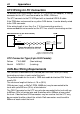
CAN Output Messages
The PDM transmits the following messages at 20 Hz.
Note: only relevant messages get transmitted for a particular PDM type
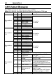
CAN Address
Byte
Bit
Channel
Scaling
Base address
+ 0
0
4..7
Compound Id = 0
0
0
Input 1 State
0 = Inactive
1 = Active
1
0
Input 2 State
2
0
Input 3 State
3
0
Input 4 State
4
0
Input 5 State
5
0
Input 6 State
6
0
Input 7 State
7
0
Input 8 State
Base address
+ 0
0
4..7
Compound Id = 1
0
0
Input 9 State
0 = Inactive
1 = Active
1
0
Input 10 State
2
0
Input 11 State
3
0
Input 12 State
4
0
Input 13 State
5
0
Input 14 State
6
0
Input 15 State
7
0
Input 16 State
Base address
+ 0
0
4..7
Compound Id = 2
0
0
Input 17 State
0 = Inactive
1 = Active
1
0
Input 18 State
2
0
Input 19 State
3
0
Input 20 State
4
0
Input 21 State
5
0
Input 22 State
6
0
Input 23 State
Base address
+ 0
0
4..7
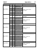
Compound Id = 3
1
0..7
PDM Internal
Temperature
0 to 125 = 0 °C to +125 °C
1 °C steps
2
0..7
PDM Battery
Voltage
0 to 255 = 0 V to 31 V
0.1216 V steps
3
0..7
Global Error Flag
0 = OK
1 = one or more outputs is in
either Fault or Over-Current error
4
0..7
Total Current
0 to 255 = 0 to 255 A
1 A steps
5
0..7
9.5V internal rail
voltage
0 to 255 = 0 V to 15.68 V
0.0615 V steps
Should read close to 9.5 V when
the Battery voltage is > 10.5 V
6
0..7
Reset Source