CML12S-DP256 Development Board for Motorola MC9S12DP256 xiom anufacturing 2000 2813 Industrial Ln. • Garland, TX 75041 • (972) 926-9303 FAX (972) 926-6063 email: Sales@axman.com • web: http://www.axman.
C M L 1 2 S D P 2 5 6 1 0 / 1 0 / 0 2 CONTENTS GETTING STARTED ........................................................................................................ 3 Installing the Software ............................................................................................4 Board Startup..........................................................................................................4 Support Software.....................................................................................
C M L 1 2 S D P 2 5 6 1 0 / 1 0 / 0 2 GETTING STARTED The Axiom CML12S-DP256 single board computer is a fully assembled, fully functional development system for the Motorola MC9S12DP256 microcontroller. Provided with wall plug power supply and serial cable. Support software for this development board is provided for Windows 95/98/NT/2000/XP operating systems. This development board applies option selection jumpers.
C M L 1 2 S D P 2 5 6 1 0 / 1 0 / 0 2 Installing the Software 1. Insert the Axiom 68HC12 support CD in your PC. If the setup program does not start, run the file called "SETUP.EXE" on the disk. 2. Follow the instructions on screen to install the support software onto your PC. You should at minimum install the AxIDE for Windows software. 3. The programming utility “AxIDE” requires you to specify your board. You should select "CML12SDP256" version of your development board.
C M L 1 2 S D P 2 5 6 1 0 / 1 0 / 0 2 At minimum, you should install the AxIDE program. This provides the flash programming utility and communication with the board via the COM port and the supplied serial cable. This program includes a simple terminal for interfacing with other programs running on the CML12Sxxx and information from your own programs that send output to the serial port.
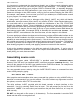
C M L 1 2 S D P 2 5 6 1 0 / 1 0 / 0 2 It is important to understand the development board's use of Memory and Addressing when writing source code so you can locate your code at valid addresses. For example, when in debug mode, you should put your program CODE in External RAM. In assembly language, you locate the code with ORG statements in your source code. Any lines following an ORG statement will begin at that ORG location, which is the first number following the word ORG, for example: ORG $4000.
C M L 1 2 S D P 2 5 6 1 0 / 1 0 / 0 2 If there are no fatal errors in your source code, 2 output files will be created: HELLO.S19 HELLO.LST a Motorola S-Record file that can be loaded or programmed into memory a common listing file which provides physical address information with resulting opcode and operand information. Warnings and error messages are provided with a summary at the end of the file. The listing file is especially helpful to look at when debugging your program.
C M L 1 2 S D P 2 5 6 1 0 / 1 0 / 0 2 You can modify the hello program to display other strings or do anything you want. The procedures for assembling your code, uploading it to the board and executing it remain the same. MON12 has many features such as breakpoints, memory dump and modify and simple program trace (no redirect of the PC is followed). Type HELP at the MON12 prompt for a listing of commands or consult the Mon12 documentation on the disk for more information.
C M L 1 2 S D P 2 5 6 1 0 / 1 0 / 0 2 MON12 OPERATION Mon12 is an embedded monitor / debug utility that allows loading a compiled software program (S record) into Ram memory for testing and debug. The monitor may control the execution of the software by applying the SWI software interrupt service. Other features allow memory and register examination or modification. Communication with the monitor is provided on the HCS12 SCI0 serial port or COM port on the development board.
C M L 1 2 S D P 2 5 6 1 0 / 1 0 / 0 2 B) Set Stack, Initialize memory map and SCI0 port and send prompt. C) Receive first character from Console port and execute monitor if ASCII text / command, else start utility mode for programming services.
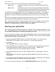
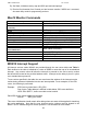
C M L 1 2 S D P 2 5 6 1 0 / 1 0 / 0 2 MON12 and NOICE Memory Map ADDRESS TYPE MEMORY MEMORY APPLICATION $C000 $FFFF FLASH MON12, NOICE, and Utility firmware located in internal flash, Page $3F. $8000 $BFFF External Ram $4000 $7FFF External Ram User Program Memory, emulate fixed page $3E. $3F8C $3FFD Internal Ram Ram Interrupt Vector Table $3E00 $3F8B Internal Ram Monitor reserved ram memory. Stacks and variables.
C M L 1 2 S D P 2 5 6 1 0 / 1 0 / 0 2 BDM OPERATION The CML12S-DP256 board will emulate supported HC12 device internal flash memory in external ram. This feature allows BDM (Background Debug Modules) such as the AX-BDM12 to load and control the execution of code being developed without the necessity of the internal flash memory being programmed many times during the development process.
C M L 1 2 S D P 2 5 6 1 0 / 1 0 / 0 2 2) After development by applying ram memory program pages $20 - $2D, user should relocate the paged program code to internal flash pages $30 - $3D for programming into the flash memory. The user code in memory area 0x4000 - 0x7FFF will translate to the lower fixed flash page $3E for programming operations. User variables and stack, as well as interrupt vectors should stay in the internal ram area 0x1000 - 0x3E80 (monitor stack and variables not needed).
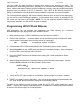
C M L 1 2 S D P 2 5 6 1 0 / 1 0 / 0 2 AUTO OFF / spare The AUTO OFF (Spare on REV C. board) option jumper installed defeats the Autostart operation so the MON12 monitor will provide a command prompt. The jumper applies a ground potential to the XIRQ* interrupt line. User should only install the jumper to restore monitor operation, perform the MON12 NOAUTO command to disable the Autostart, and remove or idle the jumper. MON12 operation will then be provided on subsequent Reset conditions.
C M L 1 2 S D P 2 5 6 1 0 / 1 0 / 0 2 CUT-AWAY OPTIONS 1 - 6 CUT-AWAY options allow the user to disconnect dedicated HCS12 I/O port resources from development board peripherals. The CUT-AWAY options also allow for establishing the connection again by installing surface mount 1206 size 0 ohm resistors or mod wire with the use of a soldering iron. Normal operation of the development board generally does not require any manipulation of the CUT_AWAY options.
C M L 1 2 S D P 2 5 6 1 0 / 1 0 / 0 2 MCU_PORT +5V PT7 PT5 PT3 PT1 ** PK0 ** PK2 ** PK4 GND PP1 PP3 PP5 PP7 ** PM1 PM3 PM5 PM7 PJ1 PJ7 ** PS7 ** PS5 ** PS3 ** PS1 GND GND ** PB7/D7 ** PB5/D5 ** PB3/D3 ** PB1/D1 GND 60 58 56 54 52 50 48 46 44 42 40 38 36 34 32 30 28 26 24 22 20 18 16 14 12 10 8 6 4 2 59 57 55 53 51 49 47 45 43 41 39 37 35 33 31 29 27 25 23 21 19 17 15 13 11 9 7 5 3 1 GND PT6 PT4 PT2 PT0 PK1 ** PK3 ** PK5 ** +5V PP0 PP2 PP4 PP6 PM0 ** PM2 PM4 PM6 PJ0 PJ6 PS6 ** PS4 ** PS2 ** PS0 ** +5V V
C M L 1 2 S D P 2 5 6 1 0 / 1 0 / 0 2 BUS_PORT GND PA2/D10 PA1/D9 PA0/D8 A0 A1 A10 OE* A11 A9 A8 A12 WE* PE3/LSTRB* PE5/MODA PE6/MODB +5V PE2/RW PE4/ECLK GND 1 3 5 7 9 11 13 15 17 19 21 23 25 27 29 31 33 35 37 39 2 4 6 8 10 12 14 16 18 20 22 24 26 28 30 32 34 36 38 40 D11/PA3 D12/PA4 D13/PA5 D14/PA6 D15/PA7 A2 A3 A4 A5 A6 A7 A13 A14 A15 PE7/NOACC ** PE1/IRQ* PE0/ XIRQ* RESERVED RESERVED RESET* The BUS_PORT supports off-board memory devices while the HCS12 is in expanded mode.
C M L 1 2 S D P 2 5 6 1 0 / 1 0 / 0 2 The 1,4,6,7,8, and 9 pins provide RS232 flow control and status. These are connected on the on the bottom of the development board to provide NULL status to the host. User may isolate pins and provide flow control or status connection to the host by applying HCS12 I/O signals and RS232 level conversion. P_COM2 P_COM2 is a 3 pin header that provides the HCS12 SCI1 serial port translated to RS232 signal levels.
C M L 1 2 S D P 2 5 6 1 0 / 1 0 / 0 2 CAN BUS TERMINATION The CAN port provides RC11,12, and 13 1206 SMT size termination resistors on the bottom of the CML12Sxxx board that are not installed at the factory. The termination resistors provide optional bias and termination impedance for the CAN bus connected to the CAN Port. Type of wire media, data rate, length of wire, and number of CAN bus nodes can all effect the requirement or value of the termination for the CAN bus.
C M L 1 2 S D P 2 5 6 1 0 / 1 0 / 0 2 1) The LCD write requires 3 SPI transfers. Transfer 1 provides data 0 - 3 and RS (register select) value. Transfer 2 provides the same data with the EN (D7) bit set. Transfer 3 provides same data with the EN bit clear. 2) Resistor R25 can be removed to apply and external VEE potential. 3) CUT-AWAY 1 - 3 provide a means to isolate the LCD Port from the HCS12 SPI channel.
C M L 1 2 S D P 2 5 6 1 0 / 1 0 / 0 2 TROUBLESHOOTING The CML12SXXX board is fully tested and operational before shipping. If it fails to function properly, inspect the board for obvious physical damage first. Ensure that all IC devices in sockets are properly seated. Verify the communications setup as described under GETTING STARTED and see the Tips and Suggestions sections following for more information.
C M L 1 2 S D P 2 5 6 1 0 / 1 0 / 0 2 Tips and Suggestions Following are a number of tips, suggestions, and answers to common questions that will solve many problem users have with the CML12SXXX development system. You can download the latest software from the Support section of our web page at: www.axman.com Utilities • If you’re trying to program memory or start the utilities, make sure all jumpers are correct.
C M L 1 2 S D P 2 5 6 1 0 / 1 0 / 0 2 TABLE 1: LCD Command and Character Codes Command codes are used for LCD setup and control of character and cursor position. All command codes are written to LCD panel address $B5F0. The BUSY flag (bit 7) should be tested before any command updates to verify that any previous command is completed. A read of the command address $B5F0 will return the BUSY flag status and the current display character location address.
C M L 1 2 S D P 2 5 6 1 0 / 1 0 / 0 2 TABLE 2: MON12 Service Routine Jump Table ADDRESS ff10 ff13 ff16 ff19 ff1c ff1f ff22 ff25 ff28 ff2b ff2e ff31 ff34 ff37 ff3a ff3d ff40 ff43 ff46 ff49 ff4c ff4f ff52 ff55 ff58 ff5b ff5e ff61 ff64 ff67 JMP JMP JMP JMP JMP JMP JMP JMP JMP JMP JMP JMP JMP JMP JMP JMP JMP JMP JMP JMP JMP JMP JMP JMP JMP JMP JMP JMP JMP JMP MAIN BPCLR RPRINT HEXBIN BUFFARG TERMARG CHGBYT CHGWORD READBUFF INCBUFF DECBUFF WSKIP CHKABRT UPCASE WCHEK DCHEK ONSCI0 INPUT OUTPUT OUTLHLF OUTRHLF
C M L 1 2 S D P 2 5 6 1 0 / 1 0 / 0 2 TABLE 3: MON12 Interrupt Table MON12 Ram Interrupt Vector HCS12 Interrupt Vector Address Vector Type 3F8C 3F8E 3F90 3F92 3F94 3F96 3F98 3F9A 3F9C 3F9E 3FA0 3FA2 3FA4 3FA6 3FA8 3FAA 3FAC 3FAE 3FB0 3FB2 3FB4 3FB6 3FB8 3FBA 3FBC 3FBE 3FC0 3FC2 3FC4 3FC6 3FC8 3FCA 3FCC 3FCE 3FD0 3FD2 3FD4 3FD6 3FD8 3FDA 3FDC 3FDE 3FE0 3FE2 3FE4 3FE6 3FE8 3FEA 3FEC 3FEE 3FF0 3FF2 3FF4 3FF6 3FF8 3FFA 3FFC FF8C FF8E FF90 FF92 FF94 FF96 FF98 FF9A FF9C FF9E FFA0 FFA2 FFA4 FFA6 FFA8 FFAA FF