CPEi 775 Series User Manual
Table of Contents Contents Chapter 1: Desktop CPEi 775 User Guide Overview . . . . . . . . . . . . . . . . . . . . Powerful Features in a Single Unit Front of the CPE . . . . . . . . . . . . . . . Back of the CPE . . . . . . . . . . . . . . . Operating Information . . . . . . . . . . .... .... .... .... .... .... .... .... .... .... . . . . . .. .. .. .. .. . . . . . . . . . . . . . . . . . . . . . . . . . . . . . . . . . . . . . . . . . . . . . . . . . . . . . . . . . . . . . . . . . .
Certificate Tab . System Tab . . . . About Tab . . . . . Wi-Fi Advanced . . . . . . . . . . . . . . . . . . . . . . . . . . . . . . . . . . . . . . . . . . . . . . . . . . . . . . . . . . . . . . . . . . . . . . . . . . . . . . . . . . . . . . . . . . . . . . . . . . . . . . . . . . . . . . . . . . . . . . . . . . . . . . . . . . . . . . . . . . . . . . . . . . . . . . . . . . . . . . . . . . . . . . . . . . . . . . . . . . . . . . . . . . . . . . . . . . . .
Desktop CPEi 775 User Guide 1 Chapter 1: Desktop CPEi 775 User Guide Overview Thank you for purchasing the Motorola CPE Indoor (CPEi) 775 desktop device. The Desktop CPEi allows you to connect to the wireless world easily and seamlessly without complicated installation and setup procedures. In addition, it offers you the ability to make Voice over Internet Protocol (VoIP) calls. The Desktop CPE indoor (CPEi) device provides the user: • Convenience - with easy plug and play functionality. Compact design.
1 Desktop CPEi 775 User Guide Powerful Features in a Single Unit The CPE device provides the following features: • WiMAX Authentication • WAN DHCP Client • LAN DHCP Server • Home Gateway Functions • Firewall Protection • Port Forwarding • Wi-Fi Front of the CPE The front of the CPE unit contains LED Link/Activity indicators. The LEDs show the status of the initialization during and network connections during power up. The LEDs also indicate the signal strength, and if Wi-Fi is enabled.
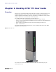
Desktop CPEi 775 User Guide 1 Back of the CPE The back of the CPE unit contains the reset switch, AC Power Connector, Ethernet connector, Ethernet LED, Line 1 and Line 2 telephone ports. Figure 1-2: CPE Ports and Connections Table 1-2 Port Descriptions Port Port Description Ethernet Ethernet Port Power AC Power Connector Reset Hardware Reset Button (A paperclip is recommended for accessing this button). Phone Line 1 RJ-11 port for use with VoIP. Phone Line 2 RJ-11 port for use with VoIP.
1 1-4 Desktop CPEi 775 User Guide 68P09301A65-A FEB 2009
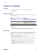
Installation 2 Chapter 2: Installation Overview To install the Desktop CPEi 775 Series, review the following sections: • Before You Begin • Easy Setup Before you Begin Before you begin installation, check that you have received the following items with your Desktop CPEi 775: Table 2-1 In the box with your CPE, you should have Item Description AC Power Adapter Power adapter cord connects the Desktop CPE to an AC electrical outlet.
2 Installation Advanced Setup The CPE can also be used to connect to a multi-port switch (hub) - purchased separately from the CPE. Connecting the CPE device to a hub allows you to connect more than one computer to your CPE device. Procedure to Log into the CPE Before you Begin Configuration Some settings on your computer need to be verified or changed to ensure that your computer configuration can support the Desktop CPE.
Installation 2 Figure 2-1: Login Screen 4. 5. 6. 7. In the Password field, type the password (default is motorola). Click Login. First time users see a pop-up box that states: “The Wizard application will guide you through for the first time configuration”. Click OK button to continue. Click the OK button to launch the wizard application. Setup Wizard and Authentication Step 1 - Change Password Once you have launched the setup wizard, you are prompted to change your password.
2 Installation • • Check the box that is called “Auto Adjust for Daylight Savings Time” if you live in a region that observes Daylight Savings Time. This box is checked by default. Click the Next button. Step 3 - WiMAX Security The WiMAX Security tab contains your authentication method. Check with your service provider to determine if they require a user name and password for authentication purposes. • If the Authentication Method is EAP-TLS, no User Name and Password are required.
Installation 2 Figure 2-2: Status Screen Restart Button Figure 2-3: Restart Button 68P09301A65-A FEB 2009 2-5
2 2-6 Installation 68P09301A65-A FEB 2009
Basic Configuration 3 Chapter 3: Basic Configuration Once the CPE setup has been completed, you can log in to your CPE from any computer on your home network. To log in type the device name in the address bar on your computer. The default device name is mywimax. This section describes the PERSONALIZE, INTERNET, STATUS, and Wi-Fi basic Menus that are available.
3 Basic Configuration Password Tab The password tab allows you to enable/disable password protection. You can also change your password here. Be sure to click the Apply button when finished . Table 3-1 Password Tab Field or Button Description Enable Login Password Protection Checking this box requires login password protection. New Login Password Enter your new password here. Maximum 20 characters. Passwords are case sensitive.
Basic Configuration 3 Restore Factory Settings Tab The Restore Factory Settings Tab resets your CPE to the manufacturers default settings. Be sure to click the Apply button if you are sure that you want to reset factory settings. Table 3-4 Restore Factory Settings Tab Field or Button Description Restore Factory Settings Checking this box restores the CPE to factory default settings. The device restarts when you click Apply.
3 Basic Configuration WiMAX Security Tab The WiMAX Security tab contains your authentication method. Check with your service provider to determine a user name and password are required for authentication purposes. Table 3-5 WiMAX Security Tab Field or Button Description Authentication Method Drop down box allows you to select either EAP-TLS (default) or EAP-TTLS/MSCHAPv2. User Name (EAP-TTLS/MS-CHAPv2 only) Enter the User Name supplied by your service provider.
Basic Configuration 3 Table 3-6 Firewall Tab Field or Button Description Enable ping from Internet Enables the CPE to respond to a ping from the Internet. This option would be enabled to allow testing only. Do not leave this enabled. Be sure to click the Apply button once you are finished. Dynamic DNS Tab Dynamic Domain Name Service (DDNS) allows a user with a non-static IP address to keep their domain name associated with an ever changing IP address.
3 Basic Configuration Figure 3-3: Status Menu Network Tab The Network tab provides any status associated with your WiMAX Wireless Broadband connection. Telephony Tab The Telephony tab provides any status associated with your telephony connection. Telephony Menu The telephony menu allows you to manage your Voice over Internet Protocol (VoIP) services. NOTE Contact your service provider to obtain VoIP service, if you do not already have this service.
Basic Configuration 3 Figure 3-4: Telephony Menu Account Tab Please consult with your service provider for these settings. The Account Tab contains the following settings: Table 3-8 Account Tab Field or Button Description Line 1 User Name If Line 1 is an active VoIP, enter the User Name as provided by your service provider. Line 1 Password Enter the Line 1 password as provided by your service provider. Passwords are case sensitive.
3 Basic Configuration Ring Tone Tab The Ring Tone tab allows you to customize ring tones for your telephone(s). NOTE You need a phone connected to your CPE to hear ring tones. Table 3-9 Ring Tone Tab Field or Button Description Default Line 1 Ring Type Use the drop-down box to select a ring tone for Line 1. The default is ringtone R0. Test Click to hear how the selected ring tone sounds. Default Line 2 Ring Type Use the drop-down box to select a ring tone for Line 2. The default is ringtone R0.
Basic Configuration 3 Table 3-10 Caller ID Tab Field or Button Description Enable Line 2 Permanent Anonymous Outgoing Call If Line 2 is your active telephone port, check this box if you would like to permanently block your telephone number from appearing on others’ Caller ID. The default is unchecked. Be sure to click the Apply button once you have made changes. Call Forwarding Tab The Call Forwarding tab allows you to manage the call forwarding features for your telephone(s).
3 Basic Configuration Table 3-11 Call Forwarding Tab Field or Button Description Enable Line 2 Forwarding on No Answer Check this box to forward calls received on Line 2 if there is no answer. This function is not available if “Enable Line 2 Basic Forwarding” is checked. Line 2 No Answer Forwarding to Number If “Line 2 No Answer Forwarding to Number” is checked, enter the telephone number you would like to forward calls to when there is no answer on Line 2.
Basic Configuration 3 Special Number Tab The Special Number tab provides a list of special dialing numbers for your VoIP Phone Service. The Special Number Tab contains the following: Table 3-13 Special Number Tab 68P09301A65-A FEB 2009 Field or Button Description Service Provider Contact Number Use this number to contact customer service for your service provider. Emergency Number Dial this number to reach local emergency services. Redial Dial this number to redial the last number called.
3 Basic Configuration Table 3-13 Special Number Tab 3-12 Field or Button Description Automatic Callback Activate Dial this number to hear the most recent call you missed and to return the call. If the number is busy, you can hang up. When the number is available, your phone will ring. Pick up your phone and the call will be connected. Automatic Callback Deactivate Dial this number to de-activate automatic callback.
Basic Configuration 3 Wi-Fi The Wi-Fi basic menu helps manage the Wi-Fi related configurations. This menu includes Basic, and Security menus. For the Advanced settings, refer to the Advanced Configuration chapter “Wi-Fi Advanced” on page 7.
3 Basic Configuration Table 3-14 Wi-Fi Basic Field or Button Description Operating Mode A pull-down list with the choices of: • 802.11b only (default) • 802.11g only • 802.11b/g Select 802.11 b/g to set the device to operate the WiFi network with both 802.11b and 802.11g wireless devices. Operating Channels A pull-down list with choices from one to fourteen (1 through 14) depending upon the country/region setting. The default range is one to eleven (1 through 11). The default channel is six (6).
Basic Configuration 3 WEP Configuration Table 3-15 WEP Configuration Field or Button Description Authentication Type A pull-down list with choices of: • Automatic • Shared • Open The default is Automatic. Two methods of authentication can be used with WEP: Open System authentication and Shared Key authentication. Choose Automatic to allow the device to automatically switch to the WEP authentication type used by the wireless device entering the network.
3 3-16 Basic Configuration 68P09301A65-A FEB 2009
Advanced Configuration 4 Chapter 4: Advanced Configuration The Advanced Configuration section describes the Port Forwarding, Local Address, and Control Panel menus. Port Forwarding Menu Port forwarding enables you to direct incoming traffic to specific LAN hosts (computers on your network) based on the protocol and port number. It is used to play Internet games or provide local services (such as web hosting) for a LAN group.
4 Advanced Configuration Forwarding Tab Click the ADD button to create additional Port Forwarding rules. The Forwarding tab contains the following selections: Table 4-2 Forwarding Tab Field or Button Description Select Select a box when you want to delete the specific row. Protocol Select TCP (Transmission Control Protocol) or UDP (User Datagram Protocol). WAN Port Start Enter the beginning port range for external network access.
Advanced Configuration 4 Figure 4-2: Local Address Menu DHCP Server Tab The DHCP Server tab enables Dynamic Host Configuration Protocol (DHCP) server functionality on the LAN, allowing the router to dynamically assign lease IP addresses to clients that connect to it from the local network.
4 Advanced Configuration Table 4-3 DHCP Server Tab Field or Button Description DHCP Ending IP Address Sets the final IP address assigned by the DHCP server. If the DHCP server runs out of DHCP addresses, users cannot access network resources. If this happens, increase the Ending IP or reduce the Lease Time. DHCP Lease Time Sets the time, in seconds, that a network computer remains connected to the gateway using its current assigned IP address.
Advanced Configuration 4 Table 4-5 Lease Reservation Tab Field or Button Description Select Select this box if you want to delete an established lease reservation. Be sure to click the Delete button once you have selected the exception to be deleted. Client Host Name Enter the client host name. The Name field is limited to 20 characters (only 5 appear in display) MAC Address Media Access Control (MAC) address. Enter the MAC address of the device.
4 Advanced Configuration Figure 4-3: Control Panel Menu Software Tab The Software tab manages the software on your CPE device. It is also where you can upgrade device software. Use the BROWSE button to browse your computer for additional software packages. Once you have located the software package/update you would like to add to your device, click the Upgrade button. You should see the available software updates in the “Available Software Packages” table.
Advanced Configuration 4 Table 4-6 System Tab Field or Button Description Language Used in User Interface Select the desired language for the user interface. The default language is English. Enable WiMAX Radio Interface Check this box to enable the WiMAX Radio Interface. Enable LED Check this box to enable the LEDs on the front of your CPE device. Auto Refresh Interval Enter, in seconds, the interval for status Auto Refresh. Valid range is 2 seconds 9999 seconds. The default value is 3 seconds.
4 Advanced Configuration Table 4-7 Wi-Fi Advanced Menu 4-8 Field or Button Description Beacon Interval Enter a value between 1 and 65,535 milliseconds. The Beacon Interval value indicates the frequency interval of the beacon. A beacon is a packet broadcast by the device to synchronize the other wireless network. RTS Threshold This value should remain at its default setting of 2347. The range is 0-2347 bytes. Should you encounter inconsistent data flow, only minor modifications are recommended.
Advanced Configuration 4 Table 4-7 Wi-Fi Advanced Menu 68P09301A65-A FEB 2009 Field or Button Description Frame Burst The default value is disabled. Frame burst allows packet bursting which will increase overall network speed though this is only recommended for approximately 1-3 wireless clients, Anymore clients and there can be a negative result and throughput will be affected. WMM Wi-Fi Multimedia is QoS (Quality of Service) for the wireless LAN.
4 4-10 Advanced Configuration 68P09301A65-A FEB 2009
Configuring TCP/IP 5 Chapter 5: Configuring TCP/IP This section contains two examples of configuring TCP/IP in a Windows environment. Most computers already have the TCP/IP configuration enabled. Use the following procedures to verify that the configuration is set up. Configure all client computers on your network for TCP/IP (the protocol that controls communication among computers).
5 Configuring TCP/IP Figure 5-2: Control Panel 3. Click Network and Internet Connections to display the Network and Internet Connections window: Figure 5-3: Network and Internet Connections 4. 5. 5-2 Click Network Connections. Skip to Step 6. If a classic view like Figure 5-4 is displayed, double-click Network Connections to display the LAN or High-speed Internet connections.
Configuring TCP/IP 5 Figure 5-4: Control Panel Classic View 6. Right-click the Local Area Connection. If more than one connection is displayed, be sure to select the one for your network interface. Figure 5-5: Network Connections 7.
5 Configuring TCP/IP Figure 5-6: Local Area Connection Properties 8. 9. On the Local Area Connection Properties window, select Internet Protocol (TCP/ IP) if it is not selected. Click Properties to display the Internet Protocol (TCP/IP) Properties window. Figure 5-7: Internet Protocol (TCP/IP) Properties 10. Be sure Obtain IP address automatically and Obtain DNS server address automatically are selected. 11. Click OK to close the TCP/IP Properties window.
Configuring TCP/IP 5 Configuring TCP/IP in Windows Vista 1. On the Windows desktop, click the Windows Logo on the left bottom corner to display the Start window. Then click Network. Figure 5-8: Network selection 2. 68P09301A65-A FEB 2009 When the Network windows appears, click the Network and Sharing Center from the action bar on the top of the window.
5 Configuring TCP/IP Figure 5-9: Network and Sharing Center 3. After you click the Network and Sharing Center, the Network and Sharing Center window displays. Follow by clicking the Manage Network Connection from the task bar. 4. The network connections appear. Drag your mouse to the Local Area Connection and right click the mouse button. A series of tasks display. Click Properties.
Configuring TCP/IP 5 Figure 5-11: Local Area Connection selection Figure 5-12: Properties selection 5. 68P09301A65-A FEB 2009 A series of protocols appear. Among them, check the Internet Protocol Version 4 (TCP/IPv4) and click Properties.
5 Configuring TCP/IP Figure 5-13: Internet Protocol Version 4 (TCP/IPv4) properties selection 6. 5-8 At TCP/IPv4 Properties window, check Obtain an IP address automatically, and Obtain DNS server address automatically. Click OK to save the settings.
Configuring TCP/IP 5 Figure 5-14: Internet Protocol Version 4 (TCP/IPv4) Properties window 7. 68P09301A65-A FEB 2009 When you have completed the setting updates, click OK to exit.
5 5-10 Configuring TCP/IP 68P09301A65-A FEB 2009
Troubleshooting 6 Chapter 6: Troubleshooting Power • • Check that the AC power adapter is properly plugged into the electrical outlet and into the Desktop CPE. Check that the electrical outlet is working. A Computer Cannot Log On to the CPE Check that the Ethernet cable is properly connected to the Desktop CPE unit and the computer. Cannot Connect to the Internet • • Check the Desktop CPE connection status from the Web Interface, refer to the Connection Status section to verify the connection status.
6 6-2 Troubleshooting 68P09301A65-A FEB 2009
Important Safety and Legal Information 7 Chapter 7: Important Safety and Legal Information Your Motorola WiMAX Wireless Broadband Gateway is designed and tested to comply with a number of national and international standards and guidelines (listed below) regarding human exposure to RF electromagnetic energy.
7 Important Safety and Legal Information • • Connect the equipment into an outlet on a circuit different from that to which the receiver is connected. Consult the dealer or an experienced radio/TV technician for help. This Gateway desktop transmitter must not be co-located or operating in conjunction with any other antenna or transmitter. FCC Caution: Any changes or modifications not expressly approved by the party responsible for compliance could void the user’s authority to operate this equipment.
Important Safety and Legal Information 7 EU Declaration of Conformity Table 7-1 For the following equipment: WiMAX 3.5GHz (Model Name: CPEi35775) WiMAX/WiFi CPE B2 Blade II 3.5 is herewith confirmed to comply with the requirements set out in the Council (European Parliament) R&TTE Directive (1999/5/EC). For the evaluation regarding this Directive, the following standards were applied: EN 302 326-2 V1.2.2 (2007-06), EN 302 326-3 V1.3.1 (2008-02) EN 301 489-1 V1.8.1 (2008-04); EN 301 489-4 V1.3.
7 Important Safety and Legal Information Disposal of Motorola Equipment in EU Countries This product is compliant with the requirements of the European Union Restriction of Hazardous Substances (EU RoHS) directive. Please do not dispose of Motorola Networks equipment in landfill sites. In the EU, Motorola Networks in conjunction with a recycling partner will ensure that equipment is collected and recycled according to the requirements of EU environmental law.
Important Safety and Legal Information 7 Copyrights and Trademarks Notice While reasonable efforts have been made to assure the accuracy of this document, Motorola, Inc. assumes no liability resulting from any inaccuracies or omissions in this document, or from use of the information obtained herein. The information in this document has been carefully checked and is believed to be entirely reliable. However, no responsibility is assumed for inaccuracies or omissions. Motorola, Inc.
7 Important Safety and Legal Information High Risk Materials Components, units, or third-party products used in the product described herein are NOT fault-tolerant and are NOT designed, manufactured, or intended for use as online control equipment in the following hazardous environments requiring fail-safe controls: the operation of Nuclear Facilities, Aircraft Navigation or Aircraft Communication Systems, Air Traffic Control, Life Support, or Weapons Systems (High Risk Activities).
MOTOROLA and the Stylized M Logo are registered in the US Patent & Trademark Office. All other product or service names are the property of their respective owners. © 2009 Motorola, Inc.